|
||||||||||||||||||||||||||||||||||||||||||||||||||||||||||||||||||||||||||||||||||||||||||||||||||||||||||||||||||||||||||||||||||||||||||||||||||||||||||||||||||||||||||||||||||||||||||||||||||||||||||||||||||||||||||||||||||||||||||||||||||||||||||||||||||||||||||
The TSEC/KL-7 is an
American offline crypto machine, developed by the
Army Security Agency (ASA) and Armed Forces
Security Agency (AFSA) under the name AFSAM-7. In
1953, the machine was introduced by its
successor, the National Security Agency (NSA) and
in 1955 renamed TSEC/KL-7. It was the first
lightweight tactical rotor crypto machine using
electronics, initially developed as standard
crypto device for the U.S. military, CIA and FBI,
and later the military and state departments of
all NATO members and some Asian countries, until
the mid-1960s. The KL-7 later served mostly as
backup, often superenciphered on other
cryptosystems, until its withdrawal from service
in 1983.
The KL-7 was a 1950s marvel of technology that combined the latest cryptologic knowledge and electronics. The cleverly designed keyboard changes the signal direction through the rotors, notch rings on the rotors control the rotor movement in a most complex fashion, and electron tubes control the timing signals for the printer. The KL-7 had excellent cryptographic properties and was designed to resist any cryptanalytic attack by the Soviets, even if the technical details were compromised. Two serious security breaches occurred in the 1960s, when U.S. Army Signals Warrant Officer Joseph Helmich and Navy Chief Warrant Officer John Walker independently compromised the KL-7 and KL-47. They sold the technical repair and maintenance manuals and secret operational key lists to the Soviets, allowing them to decrypt U.S. Navy communications, and message trafic in the Southeast Asian conflict areas. The history of the KL-7 and its
technical specifications were kept secret for
decades, and information about the machine only
gradually surfaced in recent years. This page is
a tribute to the ASA, AFSA, and NSA cryptologists
and engineers who developed the KL-7, as well as
the men who operated the machine while serving
their country around the world. You can also
download an accurate TSEC/KL-7 simulator to
experience the machine first-hand. |
|

A call
to former KL-7 and KL-47 operators, technicians,
and related signals associations and
organizations. Help us preserve cyptologic
history by sharing your personal experience with
the KL-7 or KL-47, its use in the field during
exercises or operations, and the pros and cons.
The machine is declassified, and we're not
interested in classified information. Please contact us to document your story, or spread this
call. More info on our Crypto
News. |
General Description 
The TSEC/KL-7 is an
offline non-reciprocal rotor cipher machine with
electro-mechanical and electronic components,
including electron
tubes. The machine
measures 12 x 12 x 6.37 inches (30.5 x 30.5 x
16.2 cm) and weighs a mere 20.5 lbs (9.3 kg). The
KL-7 operates on 24 volts DC to power the motor-generator (DC motor drives an AC generator).
Electrical properties:
The 24 volts to power the KL-7 could either come from batteries, as available in vehicles, or from the mains. For use on mains there is a separate AC power converter that can be set to 100-125 V or 200-250 V at 50-60 Hz, and its transformer with rectifier delivers 21 to 31V DC to the KL-7. The batteries or AC power converter output are attached to the connector of the 24 volts power cord, located at the front-right of the machine (see also electronics section). In 1955, the AFSAM-7 was
renamed TSEC/KL-7, following NSA's nomenclature.
TSEC stands for Telecommunications Security
(COMSEC), K for Crypto equipment and L for
Literal because the encrypted output is in
letters (A through Z). For components of a
machine, the TSEC comes after the item
designation. Below the NSA naming of the main
KL-7 parts, followed by the AFSA naming from its
predecessor agency. See also NSA nomenclature table
The
other important parts are the mode selector and
sliding contact board
underneath keyboard to switch the signals through
the rotors and select the different cipher modes,
the set
of rotors to perform
the encipherment and notch rings to control their
movement, the pulse generator,
the timing
unit, and one 12AX7
double triode vacuum electron tube and three 2D21 thyratron xenon gas-filled
tubes provide the
timing signals for the printer,
which prints the text or code groups on a gummed
paper tape.
|
|
||||||||||||||||
General Schematic

* Depressing a key will ground one of the pulse coils. The rotors encipher that signal on its way to the pulse generator. The encipherment is non-reciprocal and the sliding contact board must therefore switch the direction of the signal through the rotors, to select between enciphering and deciphering. When the armature of the pulse generator passes a grounded coil, that coil induces a pulse, which is passed to the Step-up Transformer, and also switches the Gate tube, which in turn enables the Print tube to receive the print pulse.
The transformer sends the pulse to the Sharpener tube, which cleans up the signal and sends it to the Print tube that activates the print hammer. However, if the Shift tube is in FIG mode, it tells the Sharpener tube to only accept high pulses from figure coils and ignore any low pulse from letter coils. The Print tube also activates the timing unit clutch, causing the timing unit to perform one single cycle in 0.1 seconds (600 rpm). This cycle controls four cam switches with timing signals for the letters and figures function, the print control circuit, and to prevent multiple cycling.
During the printing
cycle, one timing unit cam switch resets the Gate tube, which in turn
disables the Print tube, to prevent the
processing of unwanted double or stray keyboard
pulses before the rotor stepping is completed and
the machine is ready to process a new keyboard
pulse.
The notch rings on the rotors are sensed by actuator
switches of the stepping logic
that activates some of the stepping magnets.
These magnets enable drive pawls, and the timing
unit provides mechanical power to the drive pawls
to move the rotors. More details and the complete
circuitry are found in the electronics
section. |
|

Mode Selector and Sliding Contact Board
The Contact Panel
Assembly comprises spring-loaded contacts across
the bottom plate that mate with contacts at the
bottom of the keyboard, stepping unit and printer. This
modular design allows easy disassembly of all
main parts of the KL-7 for maintenance and
repair.
To switch between enciphering and deciphering, the KL-7 has a simple and compact solution to change the direction of the signals through the rotors. The keyboard contains a large Sliding Contact Board which is operated by the Selector handle with the positions O-P-E-D (Off - Plain - Encipher - Decipher). The sliding contact board with its T-shaped contacts moves from right to left between the keyboard keys and the spring-loaded contacts on the contact panel assembly. The keys are all grounded and depressing them will ground the T-shaped contact plate at the top of the sliding contact board. The selector handle has a pawl that grasps into a vertical slot on the left of the contact board. Turning the selector clockwise moves the sliding contact board from right to left. Two rails on the sliding contact board press it down onto the spring-loaded pins, meanwhile ensuring smooth movement of the contact board. The sliding contact board also contains the main power switch. The KL-7 power cable with connector (on the right) passes the radio interference filter (vertical block right-side machine), enters at the right-side top of the keyboard (see flipped keyboard) and connects to two slide contacts that touch two copper stripes (double-T contacts) at the far right of the contact board. The board also switches various parts of the electronics. |
|
")

In Encipher mode, the depressed G key is connected via the T-shape and its GE contact to the EG (Encipher letter G) contact on the left side of the cipher unit that holds the rotors, exits at the DH (Decipher H) contact on the right side, passes the small connecting bar of the H key and continues from its Print contact to the H pulse coil.
In Decipher mode, the depressed H key is connected via the T-shape and its HD contact to the DH (Decipher letter H) contact on the right side of the cipher unit, exits at the EG (Decipher G) contact on the left side, passes the connecting bar of the G key, and continues from its Print contact to the G pulse coil.
The use of two neighboring T-shapes for each key enables the O-P-E-D sequence from right to left. The above is a simplified example with 3-pin rotors. In reality, the KL-7 uses 36-pin rotors. Note that, to perform the piggyback functions, some E, P and D connections from “J”, “V”, “X”, “Y”, “Z”, SPACE, FIG and LET are swapped, and additional contacts on the sliding contact board switch some piggyback wires and other control functions.
 Important note on direction of current!
The arrows in the above image are only used to easily
visualize how the keys are connected to the pulse coils. In reality, the current travels in the
opposite direction! Each pulse coil generates its own
current when the armature of the pulse generator passes
that coil. The positive side of the coil is connected
through the key contacts and rotors to the common.
However, this is not actual "grounding" of the
signal in the usual sense.
Important note on direction of current!
The arrows in the above image are only used to easily
visualize how the keys are connected to the pulse coils. In reality, the current travels in the
opposite direction! Each pulse coil generates its own
current when the armature of the pulse generator passes
that coil. The positive side of the coil is connected
through the key contacts and rotors to the common.
However, this is not actual "grounding" of the
signal in the usual sense.
A pulse coil only uses the common to transport its signal to the step-up transformer, which inverts the signal before it is processed by the electronics. Within the circuit, each pulse coil can be considered as a separate power source with its own circuit.
When a key is depressed, and depending on the Selector position, the positive side of the coil that represents its enciphered or deciphered version is connected to the general common. When energized, the coil sends its positive signal through the "common" and the step-up transformer (in opposite polarity) to end its route at the negative side of the same coil (see red arrows). See also the complete electronic circuit and timing signals.
How can depressing key G, connected to EG on the left of the rotor pack, ground the correct coil to print the encrypted letter H? For a given position and wiring of the rotors, when EG is connected to DH, then DH is also connected to EG. In fact, to encrypt the letter G, the KL-7 does not "encrypt" the letter G but grounds the letter G, and by doing so, the rotor pack grounds its counterpart DH, which is connected to the H coil that is energized by the pulse generator and sends the signal to print the letter H.
Since EG and DH are reciprocal, this works also for decryption. However, this is only true for this particular position of the rotors, which changes after each letter of the message. This is what makes the KL-7's sliding contact board so clever. This is also why in the first example the black arrows are opposite to the actual direction of the current, because following the path, starting from the H coil, seems illogical when you must first depress key G.
The sliding contact board also switches some additional functions in the electronic circuit. Also, depending on the selected mode, the signal from some keys, involved in the piggyback system, is rerouted. The board also has a notched part in front of the printer mechanism. With the mode selector in Encipher position, this cam pushes a pin into the printer mechanism, causing the KL-7 to print a space after each fifth character, the standard format for cryptograms.
* Note on contact problems. Passing the signal from a depressed key to a pulse coil requires many contact points to work flawlessly (a contact point is where two switching or sliding contacts make contact). In Plain mode, there are only two contact points: key to sliding contact board and from there to contact panel assembly p contact, connected directly to the pulse coil. In Encipher or Decipher mode, there are 13 contact points: one from key to sliding contact board, one to contact panel assembly, 9 through the rotors, and two contacts on the sliding contact board's small bridge, connected to the pulse coil.
However, for each time that the signal exits the rotor cage at one of the re-entry contacts, an additional pass through the rotors adds 9 contact points to the signal path. Theoretically, up to 10 additional passes are possible, thus adding 90 additional contact points. Also, using the LET or FIG key in Encipher or Decipher mode will add two additional contact points on the Letters Cam switch or Figures Cam Switch. In any mode, one single failing contact will prevent the machine from processing the character and stepping the rotors to process the next letter. This is the notorious so-called dead-rove, usually caused by poor maintenance. Regular and thorough cleaning of the rotors and keyboard contacts was therefore essential.
There are 324 contact points between the eight rotors mutually, and the rotor contact plates from the cipher unit. Between the keyboard and the top of the sliding contact board are 29 contact points (letter keys, FIG, LET and SPACE). Between the bottom of the sliding contact board and the top of the contact panel assembly are 119 contact points. In total, 472 contact points move (rotors, sliding contact board) or switch (keyboard keys). This does not take into account the numerous contacts between the bottom of the modular parts (motor-generator, pulse generator, stepping unit) and the top of the contact panel assembly. These are less prone to dirt because the modular parts are fixed onto the contact panel assembly and are only removed when a module is defective or requires maintenance. The only exception is the cipher unit, removed daily to load the new rotor settings.
TSEC/HL-1 Tape Reader and KLX-7 Keyboard Adapter
An optional TSEC/HL-1
Tape Reader was available for the KL-7. In NSA
nomenclature, the H means ancillary device that
helps processing, and L means letters output. The
HL-1 reads 5-bit punched tapes with plain or
ciphertext and sends it to the KL-7. This enables
fast processing of message tapes, received from,
or created on a standard teleprinter, avoiding
the laborious manual typing of messages on the
KL-7.
The use of the HL-1 tape reader requires the KLX-7/TSEC Keyboard Adapter, mounted between the keyboard and the Sliding Contact Board. The installation of the KLX-7 therefore requires the removal of the KL-7 keyboard cover. To install the KLX-7, the Mode Selector must be in Decipher position. The five screws of the keyboard are removed, the keyboard is lifted without moving the Sliding Contact Board, and the standoffs are removed. The KLX-7 is placed on the contact panel while ensuring its Selector handle extension engages in the notch of the Sliding Contact Board. The KLX-7 is then fixed with screws in its five hex nuts. Finally, five standoffs are placed in the hex nuts, and the keyboard is fixed back onto the chassis by tightening its screws into the standoffs. Once the KLX-7 is installed, its connector is located at the center front, just underneath the KL-7 keyboard. The KLX-7 board has 30 pressure contacts with their caps through the upper part of the board. Each of these contacts is connected to the KLX-7 connector. Also, two contacts connect the two sliding 24 volts power contacts from the KL-7 to the KLX-7 connector to pass the 24 volts to the HL-1. Moreover, depending the KL-7 Mode Selector position, a 24 volts signal is sent to the HL-1 to either process letters, figures and spaces in Plain and Encipher mode, or only letters in Decipher mode, and ignore all other 5-bit characters on the tape. The HL-1 Tape Reader senses 5-bit punched tape and converts the bits, through a series of relays, into connecting the common to one of the 26 letters, space, LET or FIG wire, and passes that common through the adapter cable to the KLX-7 adapter underneath the keyboard. This has the same effect on the KL-7 as depressing the keyboard key and grounding its corresponding pulse coil(s).
Note
on drawing: In reality, the TSEC/HL-1 is as wide
as the KL-7, and the connector on the HL-1 side
is about twice the size of the connector on the
KLX-7 side. The connector also has an alligator
clip for grounding. Before 3-wire sockets became
standard, this clip was fixed onto some metal
part near the socket. More on the HL-1 tape
reader at Jerry Proc's
Crypto Machines |
|


The Rotors and Notch Rings
 The enciphering in the KL-7 is performed by
eight rotors. These are set according to the key list. Each individual rotor performs a substitution
cipher. The rotor core wiring is still classified, and
most surviving rotors are either stripped of their
wirings or inaccessible.
The enciphering in the KL-7 is performed by
eight rotors. These are set according to the key list. Each individual rotor performs a substitution
cipher. The rotor core wiring is still classified, and
most surviving rotors are either stripped of their
wirings or inaccessible.
Its wiring was also changed on a regular basis, in contrast to, for instance, the German Enigma where the wiring never changed during its whole service time (the U.S. cryptologists learned the lessons). The KL-7 rotors were easily rewired manually by simply plugging the contacts into other positions without the need of soldering. These were designated by NSA as Red Rotors. Due to persisting problems, these were replaced by the Orange Rotors in 1956.
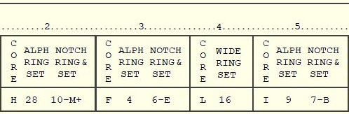
The KL-7 had a set of 12 rotors to choose from, later expanded to 13, labelled "A" through "M". (see CORE on part of the key list on the right). Each rotor core has 36 flat contacts on the left side (as seen in cipher unit windows) that are wired in a scrambled fashion with 36 spring-loaded contacts on the right side. The wiring performs a substitution encipherment. An adjustable black alphabet ring is attached to the rotor core. These letters are visible through the little windows of the cipher unit. The drive-pawls from the rotor stepping unit use the notches on the alphabet ring to advance the rotors.
The side of the alphabet ring is also marked with the numbers 1 through 36. By depressing the alphabet ring, it can rotate relative to the rotor core wirings. This is done by aligning an alphabet ring number with the white arrow on the side on the rotor (ALPHA RING SET). The 36 positions on all alphabet rings are labelled as shown in the table below. Note that 10 of the positions on the alphabet ring are left blank.
| Rotor Labels | A | B | C | D | E | F | G | H | I | J | K | L | M | N | O | P | Q | R | S | T | U | V | W | X | Y | Z | ||||||||||
| Numbers aside | 1 | 2 | 3 | 4 | 5 | 6 | 7 | 8 | 9 | 10 | 11 | 12 | 13 | 14 | 15 | 16 | 17 | 18 | 19 | 20 | 21 | 22 | 23 | 24 | 25 | 26 | 27 | 28 | 29 | 30 | 31 | 32 | 33 | 34 | 35 | 36 |
The KL-7 also has a set
of 11 white plastic notch rings. The notches and
cams on these rings control seven stepping
switches in the rotor stepping unit. They are responsible for the highly
irregular movement of the rotors. These notch
rings were also part of the key settings.
The notch rings are labelled 1 through 11 on their side, at the right of a little black arrow (NOTCH RING & SET number). The notch rings are attached to any of the rotor cores by aligning the black arrow of the notch ring with the little hole near the edge of the rotor, then depress and align the notch ring with the required letter on the alphabet ring (NOTCH RING & SET letter). Since there are some blanks on the alphabet ring, these positions are marked on the key list as the letter on its left with plus sign (e.g. position 18 is M+). As part of the key settings, a selection of seven notch rings is attached to the seven moving rotors. The stationary non-moving rotor, at the fourth position in the cipher unit, must always carry the special wide ring and is aligned according to the key list (WIDE RING SET). The rotors had persistent contact problems, caused by particles from the beryllium copper contacts that wore off and turned into non-conductive abrasive copper oxide. The beryllium copper dust particles are toxic and inhaling these should be strictly avoided. More on the rotors in the development section. |
|

The Cipher Unit
* The detachable KLK-7 Cipher Unit, also
called rotor cage or basket, holds the eight rotors that are selected from the key list.
The KL-7 uses a complex re-entry system that can
cause multiple enciphering of a single character.
Note that the re-entry drawing is a simplified example with three 6-pin rotors and 2 re-entry connections. In reality, the cipher unit holds eight 36-pin rotors and has 10 re-entry wires. Moreover, the 36 wires from the end plates are connected in a scrambled order to the flat contacts at the bottom of the Cipher Unit. (see table base and end plate connections below). When the signals leaves the exit rotor, there are two possible situations. The signal is either is passed directly to the pulse generator through one of the 26 wires, or leaves the exit rotor through one of the 10 re-entry contacts. In the latter case, the signal is rerouted back to one of the entry rotor's 10 re-entry contacts to perform an additional pass through the rotors, which can repeat multiple times before arriving at the Pulse Generator. Depending on the internal wiring and current position of the rotors, the signal performs 1 up to 11 passes through the eight rotors before leaving the exit rotor towards the pulse generator. Each stepping of the rotors results in a new and most complex signal path that changes in both number of passes and its route through the eight rotors. The cipher unit has on the left a fixed end plate with axle to slide the rotors onto, 36 spring-loaded contacts in a circular fashion on the inside, and at the bottom 26 flat contacts and 10 flat re-entry contacts. The removable end plate on the right has 36 flat contacts in a circular fashion on the inside, and at the bottom 26 flat contacts and 10 flat re-entry contacts. The 26 flat contacts on both endplates make contact with spring loaded pins on the Base, which are connect to the 26 letters from the sliding contact board. The 10 flat re-entry contacts make contact with spring loaded contacts on the rotor stepping unit that connects the wires of both sides straightforward between left and right, i.e. 0-0, 1-1, 2-2 and so on, to act as re-entry loops. |
|
|
Once all rotors are inserted, the cipher unit is placed in the rotor stepping unit and fixed with two locking levers at the front left and right of the stepping unit. The table below shows the wiring order between base and cipher unit end plate pins. The pins are numbered clockwise (seen from the left) and pin 01 is aligned with the white index stripe on the cipher unit windows. Both cipher unit end plates are wired identically. The letter “Q” from the sliding contact board wired to end plate pin 01, letter “P” to pin 02 and so on. The digits 0 through 9 represent the re-entry wires. |
|


| Base connections | Q | P | 0 | N | F | C | 3 | Y | O | M | 9 | G | R | 8 | U | I | 7 | B | H | 2 | V | T | W | 6 | X | S | 4 | J | L | Z | 5 | D | K | E | A | 1 |
| End Plate Pins | 01 | 02 | 03 | 04 | 05 | 06 | 07 | 08 | 09 | 10 | 11 | 12 | 13 | 14 | 15 | 16 | 17 | 18 | 19 | 20 | 21 | 22 | 23 | 24 | 25 | 26 | 27 | 28 | 29 | 30 | 31 | 32 | 33 | 34 | 35 | 36 |
The Pulse Generator
When a key is depressed, the pulse generator converts the signal that passed through the rotors and the keyboard into accurate timing signals for the electronics to control the printer and to activate the clutch of the timing unit, which also provides mechanical power to the rotor stepping unit.
The print hammer must activate at the exact moment a given letter on the rotating printer drum passes the hammer. To achieve this, the pulse generator provides exact timing. It consists of a magnetic armature, rotating clockwise at 2200 rpm, and two stators with pulse coils. The print wheel with all letters and figures rotates on the same axle. When the electronics receive a pulse from a coil it will activate the print hammer at the appropriate moment. There are 37 coils for 26 letters, 10 figures and the space.

The
front stator has 19 coils. The rear stator has 18
coils and is positioned exactly behind the front
stator. The rotor armature (blue at above image)
has two separate magnetic poles, one for each
stator. The rear pole lags 9.47 degrees behind
the front pole. This ensures that only one coil
at a time is induced, the front coil first and
rear coil following.
The KL-7 combines the 10 figures with 10 letters in the top row alpha-numeric keys. The electronics must therefore detect the difference between printing a letter or its corresponding figure. To do so, the alpha-numeric keys have two coils in series, a negative 5 volts low pulse coil (green) for letters and a negative 10 volts high pulse coil for figures (yellow). One special coil combination is the letter V low pulse coil in series with the SPACE high pulse coil and a junction between the coils. These are part of the piggyback system. All other letters have a single negative 10 volts high pulse coil (red). The difference between the low and high coils is the size of their core and winding. Note that the red and yellow high pulse coils are identical and only differ in color to distinguish letter and figure coils in the drawing. Depressing a key grounds its corresponding coil, generating a transient pulse that activates the Gate tube. The Gate tube determines the time frame in which the Print tube is allowed to process a character pulse. This ensures that only the current pulse activates the Print tube, and any following stray pulses are ignored. For more details on the generation of pulses, see signal timing. The common - negative - side of the pulse coils is connected to the step-up transformer. When the pulse generator armature passes the grounded coil, it will induce a pulse. The 1:3 step-up transformer inverts the negative pulse phase and raises the -5 to +15 volts or -10 to +30 volts to prepare the pulse for the Sharpener tube control grid (see images). The Sharpener tube passes the cleaned-up pulse to the Print tube. To conduct, the Sharpener tube control grid potential must be higher than the tube's cathode potential. If the control grid potential is lower than the cathode, this represents a negative bias, and the Sharpener cannot conduct. To make the Sharpener conduct, the incoming positive pulse on its grid must overcome or "pull up" the negative bias enough. This negative bias acts as a threshold (i.e. hurdle) enabling the Sharpener tube to distinguish low and high pulses. More on how the electron tubes work is found in the electronics section. The Shift tube holds the current shift mode. In LET mode, the Shift tube puts 8 volts on the Sharpener cathode. Without pulse, the transformer grounds the Sharpener grid to 0 volts, causing a minus 8 bias (0 - 8 = -8). In FIG mode, the Shift tube increases the Sharpener cathode potential to 22 volts, causing a minus 22 bias (0 - 22 = -22). In LET mode, the default minus 8 volts bias is a low threshold and the Sharpener tube will accept both high pulse letters ( -8 + 30 = +22) and low pulse letters from the alpha-numeric double-pulse (-8 + 15 = + 7) but its associated high pulse figure, although high enough ( -8 + 30 = +22), does not trigger the Sharpener tube because the tube's 11 ms recovery time is longer than the 2.88 ms between the two pulses (only one coil distance, e.g. Q and 1). In FIG mode, the Shift tube increases the bias to approximately minus 22 volts, resulting in a higher threshold. The Sharpener tube then ignores the alpha-numeric low pulse letters as they don't pass the threshold (-22 + 15 = -7) and will only react on alpha-numeric high pulse figures (-22 + 30 = +8). The following situations will occur when depressing any key:
The Gate tube prevents repeating or stray pulses, but not using this function also enables the repeat key. The RPT repeat key forces the Gate tube to keep the Print tube ready. When pressing the RPT simultaneous with another key, that character is printed continuously. Depressing a key will always activate the printer and the timing unit clutch. Note that the space key only activates the clutch and advances the paper one step without printing, and the space and piggyback letters are swapped and print other characters, depending on the state of the sliding contact board (see also letters and figures). |
|


The Printer
The fixed pulse coils
for 26 letters, 10 figures, a space and blank are
placed clockwise on the pulse generator.
with the double stator alternating between front
coil first and rear coil behind it, in the order
as shown below, starting with the Q front coil at
the top (space and blank represented by a dash).
QPWO1029EIRU3847TYZK56XHAGSFNDMCLBJV-- The KL-7 has a continuously clockwise rotating print drum at 2200 rpm, fixed on the same axle as the pulse generator. The print drum has the same character sequence on its circumference, but counterclockwise, which is the exact reverse order to the pulse coils. This seems counterintuitive. However, seen from the front, the clockwise rotating print drum passes the print hammer at the bottom from right to left. The characters Q, P, W, etc. must therefore pass one by one at the bottom, from right to left. Thus, the characters Q, P, W, etc. are placed at the bottom of the print drum from left to right, i.e. counterclockwise. The moment the magnetic armature of the pulse generator passes a grounded coil, the transformer, Sharpener and Print tube pass this signal to the print hammer and the timing unit clutch. The print hammer pushes the paper and inked ribbon upwards against the print drum, at the exact moment that the required character passes the print hammer. The two ink ribbon spools are behind the removable black cap. A pin, controlled by the sliding contact board, mechanically switches between continuously printing (plaintext) and five-letter groups with a space between each group (ciphertext). The paper roll is stored in the black circular casing between the motor block and the cipher unit. |
|

The Timing Unit
The timing unit
controls four cam switches that generate timing
signals for the electronics,
provides mechanical power to advance the paper
strip, the ink ribbon, and the pawl system of the
rotor
stepping unit to
advance the rotors. The timing unit clutch is
engaged by the trip magnet.
When the Print tube energizes the trip magnet, its rod* (yellow) is briefly removed from under the clutch pawl stop bulge* (light green). The spring-loaded clutch pawl can now move inward and its single tooth (light green) grabs into the clutch drive gear (dark blue), connecting the running DC motor through the gears to the camshaft (in reality, the trip magnets are located directly underneath the clutch). Once a revolution is completed, the clutch pawl arrives back at its original position above the meanwhile returned rod, which now pushes the clutch pawl back upwards, causing the clutch pawl single tooth to disengage from the gear. As the gears have an 11:1 motor/timing ratio, the timing unit performs one single revolution at 600 rpm in 0.1 second. During this cycle, the four cam switches send their timing signals to the electronics, and the paper strip and ink ribbon move one step further. The rotation of the timing unit and cam switches is in sync with all other mechanical processes of the KL-7. Also during this cycle, only those rotors that have been released by their associated stepping magnet are advanced one step. Thanks to the timing signals, the electronics know when the mechanical cycle has been completed. The cam switches on the timing shaft control the following functions:
More about the cam switches in the electronics section. |
 |
The Motor-Generator
 The motor-generator, providing both mechanical
power and AC voltage, is a combination of a 24 volts DC
motor and a 400 Hz AC power generator delivering 5
Watts and 150 volts rms at 6600 rpm, together in one
single housing.
The motor-generator, providing both mechanical
power and AC voltage, is a combination of a 24 volts DC
motor and a 400 Hz AC power generator delivering 5
Watts and 150 volts rms at 6600 rpm, together in one
single housing.
The motor exists in two versions. The CE 87420 was replaced from serial number 13149 by the improved CE 88000. The difference is how the current through the field winding is controlled.
The components to control the motor speed are not included in the general electronics because the controller assembly is housed inside a cover at the back of the motor-generator (see image, resistors in ohm, capacitor in microfarad).
The CE 87420 is a shunt wound DC motor where the armature and shunt field are connected parallel, which typically produces a modest starting torque but has good speed stability under varying load because its speed is self-regulated.
When the speed of the rotating armature drops, the counter-electromotive force (CEMF) also drops and more current can flow through the armature, increasing torque and motor speed. When speed rises, the CEMF also rises and less current can flow through the armature, decreasing motor speed. This feedback creates better speed stability.
The motor speed is adjustable by changing the current through the field winding, which also changes the amount of CEMF and thus motor speed. This is done by the adjustable resistor R202 to compensate manufacturing variations of the field winding and the NTC resistor R201 (Negative Temperature Coefficient).
The newer CE 88000 is also a shunt wound DC motor with self-regulating speed but has an additional centrifugal “governor” switch to maintain a constant speed while operating at voltages ranging from 21 to 31 volts DC. The Governor speed adjustment is set at 6600 +/- 100 rpm.
The governor switch is open when motor speed is low. Resistors R135 and R136 are then in series, causing a lower current through the field winding. The resulting lower CEMF speeds up the motor. When the motor reaches its optimal speed, the governor closes and short-circuits R135. The resulting higher current through the field winding causes a higher CEMF that slows down the motor.
The motor speed is adjustable with the upper screw on the governor. The lower screw adjusts the air gap between the contacts. Capacitor C121 suppresses sparks on the governor and R136 limits current surge when the governor closes.
The AC
generator is mounted in front of the motor on the same
shaft. The generator rotor is a permanent magnet that is
also fixed to the shaft. The rotating magnet induces the
high voltage in the stationary stator windings.
The Rotor Stepping Unit
The KLA-7 rotor
stepping unit supports the cipher unit (rotor cage) and controls the stepping
of the rotors. At the rear of the cradle, there
are eight large stop pawls that prevent any
non-moving rotor from moving along with
neighboring moving rotors. The fourth stop pawl
normally isn't used but keeps that fourth rotor
in place when testing the rotors on a special
axle without the rotor cage shell.
In the middle of the cradle are seven drive pawls to advance the rotors by grasping the notches in the rotor alphabet ring. These pawls are mechanically powered by the timing unit, under control of seven stepping magnets from the stepping logic. In front of the drive pawls are seven tiny cams from actuator switches that read the notch rings on the rotors. These pile-up switches control the stepping logic for the stepping magnets. Just before the cradle are seven Set Key buttons to manually advance each individual rotor. When a key is depressed, the pulse generator passes the signal to the Print tube which in turn will activate the timing unit that executes a single cycle. The stepping of the rotors is mechanically driven by the timing unit side shaft that rotates the crankshaft assembly for the rotor stepping unit. The crankshaft assembly has an eccentric crank pin, connect to the drive link assembly to convert the rotation into a back-and-forth movement that is passed to the drive shaft by the rotor stepping crank. There are 7 ball-bearing roller cams fixed to the drive shaft, or one for each moving rotor (forth rotor doesn’t move). The roller cams hold the drive linkage forward. When the timing unit cycles, the drive shaft rotates 75 degrees in clockwise direction and the 7 rollers move downwards, away from the 7 drive linkages. Each drive linkage has a spring that pulls the linkage backwards. However, when the stepping magnet of an associated drive linkage is not energized, the magnet prevents that drive linkage from moving backwards. During a cycle, some of the stepping magnets are energized by the stepping logic, under control of the 7 actuator switches. When a stepping magnet is energized and the drive shaft turns the roller cams away from drive linkages, the associated drive linkage moves backwards, causing its drive pawl to move backwards. At the same time, the drive linkage also releases the associated stop pawl, which is then pushed downwards by the stop pawl spring to enable its rotor to move. Simultaneously, the drive pawl sloped end slides backwards out of the alphabet ring notch. When the drive pawl arrives at the next notch, the small spring on the drive linkage will force the drive pawl upward into the next alphabet ring notch. |
|


When the drive shaft has reached its maximum swing angle backwards, the roller cams return forward and push any released drive linkages back to the forward position. The flat end of the drive pawl pushes its rotor one step further. The drive linkage also forces the stop pawl upward into a free alphabet ring notch. During any stepping cycle, these stop pawls prevent non-moving rotors from moving along by the friction of moving neighboring rotors.
On the right of the drawing are the 7 actuator switches that sense the white notch rings on the rotors. In the Plain mode, the operator can use the 7 Set Key buttons to manually step the individual rotors and set them in the proper position (see procedures enciphering and deciphering). During enciphering and deciphering, each key stroke causes some of the rotors to step in a highly irregular fashion under control of the 7 actuator switches.
In the circuit diagram below, all actuator switches are shown inactive. Each switch is a pile-up of the two sections, Sa and Sb. Note that the order of the upper Sa section is as actually positioned in the rotor stepping unit. The order of the lower Sb section and the stepping electromagnets is mixed to make the circuit diagram more readable, and these are actually placed from left to right according to their number. There are only 7 switches and stepping magnets because the stationary fourth rotor is skipped. The pins on all switches are numbered the same as on switch S301a and b.

The stepping circuit is
powered by the same 24 volts DC that powers the DC motor and the tube filaments.
The switch (orange) is part of the sliding contact
board and determines
which part of the circuit is powered, depending
on the cipher mode.
In Encipher (E as shown in drawing) and Decipher (D) mode, only the upper Sa section of the switch pile-up, used for sensing the notch rings, is powered (route K1 - K12 or K10 - K11 - A3 - B3). Magnets 2 through 6 are each controlled by two switches in OR logic. These magnets are activated when at least one of the two switches has the appropriate state. Magnets 1 and 7 are controlled by three switches and are activated when one switch is inactive AND at least one of two other switches is inactive. At least two magnets are always active at any given moment. In Plain mode, only the lower Sb section is powered (route K1 - K12 - K13 - A4 - B4). Depressing a Set Key button first energizes its stepping magnet through contacts 4 and 2 to release the corresponding drive linkage. A fraction later, contact 4 is pushed further down against contact 1 and energizes the trip magnet, causing the timing unit to perform a cycle and provide mechanical power to step the corresponding rotor. If the Set Key button is still held down after completing the cycle, the rotor will continue to step until the button is released. The stepping logic is wired in such a way that a situation where none of the rotors move is avoided as this would cause the rotors to halt permanently. The logic table on the right shows the required notch combinations to move a rotor. The stepping of a single rotor is controlled by two or three separate notch rings. Two notch rings can produce a maximum period (unique movement sequence) of 1,296 and three rings a maximum period of 46,656. This is for one single rotor. The combination of seven notch rings therefore provides a most complex stepping sequence. |
|
Letters and Figures
To enable enciphering 37 different characters into letter-only code groups, the KL-7 uses a system, similar to the teletype code. Two signals, LET and FIG, switch the machine between letters and figures. Both character sets use the same signals, and they are distinguished only by the FIG or LET mode on that particular moment. To show the current state, a neon bulb lights up when the KL-7 is in FIG mode. The characters “QWERTYUIOP” are processed as “1234567890” in FIG mode.
This still gives 26 alpha (-numeric) keys, the additional SPACE, LET and FIG. The KL-7 must encipher these three additional characters into a letter. Therefore, the KL-7 design permits the special functions to piggyback on some of the existing alphabet letters. The letters “J”, “V”, “X”, “Y” and “Z” were selected because they are some of the less frequently used letters.
|
|

To accomplish the piggyback of the SPACE key on letter Z, the sliding contact board reroutes the X, Z and SPACE signals. The following drawings explain the rerouting of those letters in the different modes.
Notes:
1. Below, any unspecified letter, key
or pulse coil (A through Z) is denoted by Δ (delta). Underneath each key
are three contacts, named e-p-d (encipher - plain -
decipher. Thus, the contacts underneath the A key are
named Ae, Ap and Ad. The left side contacts of the cipher unit that holds the rotors are named EA through EZ
(Encipher this letter) and the right-side contacts are
named DA through DZ (Decipher this letter). See sliding contact board for routing through rotors.
2. The actual direction of the current is opposite to the
direction of arrows in the diagrams, because the pulse
coils produce a negative pulse. The arrows are used
solely to demonstrate the path from key to transformer.
See pulse
timing signals for more
details.
 Plain Mode
In plain mode, the p-contact of each key is connected to its corresponding pulse coil (black route). Zp to the Z coil and Xp to the X coil. Both are high pulse coils (red). Depressing the letter Z or X will close the circuit of its corresponding coil. When the magnetic armature of the pulse generator passes that coil, the induced signal is stepped up by transformer T101, passed to the sharpener and print tube, and printed.
The SPACE key is connected to a junction on the V-SPACE coils pair. This special feature is also used in the separate FIG circuit. By using the junction, depressing the SPACE key will only close the SPACE coil circuit.
All other keys are also connected via their p-contact to the corresponding pulse coil. These coils can be high pulse letter coils (red) or low pulse alpha-numeric coils (green). The low pulse V coil from the V-SPACE pair is connected to the V key's Vp contact.
In plain mode, the signals do not pass
through the rotors in the cipher unit.
 Encipher Mode
In encipher mode, the e-contact of each key is normally connected to the corresponding E-contact on the cipher unit left side. This however is not the case with the piggyback Z key.
The Z and X key e-contacts (red route) are now both switched to the EX-contact (Encipher X) on the cipher unit left side. This doesn't affect the X, but the letter Z also becomes X, because the SPACE needs the Z to piggyback.
Therefore, the SPACE key's e-contact (blue route) is connected to the cipher unit left side EZ-contact and actually enciphers the letter Z that will represent the SPACE.
The enciphered version of all letters exits the cipher unit right side at one of the D-contacts. This can be any of the 26 letters DA through DZ, even the depressed key itself, depending on the rotor positions and wiring.
The signal then travels to the key that
corresponds with the cipher unit's D-contact, enters that
key's d-contact, passes its small connecting bar and its
p-contact to the pulse coil, and prints the enciphered
letter.
 Decipher Mode
In decipher mode, the d-contact of each key is connected to the corresponding D-contact on the cipher unit right side (black route). The only exception is the SPACE key, which is not used, as only letters are to be deciphered.
The deciphered version of all letters exits the cipher unit left side at one of the E-contacts. This can be any of the 26 contacts EA through AZ, even the depressed key itself, depending on the rotor positions and wiring.
The signal then travels from that E-contact to the key that corresponds with the deciphered letter, enters that key's e-contact, passes its connecting bar and p-contact to the pulse coil, and prints the deciphered letter.
When a depressed key represents the enciphered X, the signal exits the cipher unit as deciphered letter X on the left side EX-contact. The signal (red route) then travels to the Xe contact and via a connecting bar to the X coil, to print the X. Thus, both originally plain X, and the Z (changed into X) are deciphered and printed as X.
When the depressed key represents the enciphered Z, the signal exits the cipher unit left side as deciphered Z at the EZ-contact. Since the deciphered Z actually represents a SPACE, the signal (blue route) does not travel to the Ze contact, but via the SPACE Key's e-contact and connecting bar to the SPACE coil to print a space.
The Electronics
The KL-7 can be powered in two ways. The Power Cable, connected to a 24 volts DC source (e.g. vehicle battery) or the AC Power Converter that converts 110V or 220V AC into 21 to 31 volts DC (24 volts is ideal). Both power cable and converter have an Amphenol AN 3101A Mil Spec connector (2 pins female) with AN 3057-4 cable clamp that mates with the KL-7's power cable with male connector. The Power Converter has two fuse holders at the back, with one fuse to protect the circuit and one spare fuse.
CE 87066 Power
Converter |
|
The AC Power Converter
has a switch to select the AC input voltage. For
100-125 volts, the two primary windings are
switched parallel (routes 1w2-11-14-15 and
1-13-12-3w4). For 200-250 volts, the primary
windings are switched in series (route
1w2-11-12-3w4). Since the primary windings
switched in series have twice as many turns as in
parallel, the output voltage is inversely halved
and thus remains 24 volts.
The secondary winding is connected to two selenium full-wave bridge rectifier stacks connected parallel. The first version of the power converter produced 2.4 Amps output current. The newer version with 4.5 Amps (as of sn15413) is more efficient for the KL-7 with second generation motor-generator with governor switch. The higher current is also better when the selenium rectifiers are aging. The AC Power Converter measures 10.6 x 4.7 x 4 inches (27 x 12 x 10 cm). |
|
The
KL-7 itself has a power cable with AN 3106A
connector (2 pins male), connected to the Radio
Interference Filter which is mounted in
the right-side rack (see photo mode
selector). From the
filter, a short cable enters the KL-7 at the
right-side top of the keyboard. Via two fuses and
two slide contacts, the 24 volts arrive at the
double T contacts (see also circuit diagram
below). The rack also carries a dummy female
connector to secure the power cable during
transport.
The filter suppresses voltage variations on the power cable as these can cause interference on the mains grid or even piggy-back on the modulated signals of nearby radio equipment, leaking signals that could be exploited by the adversary, even at great distance. The Pi-type filter attenuates these signals over a wide band of frequencies. The filter assembly was sealed, and maintenance or repair was not allowed. If the filter malfunctioned, the complete filter assembly had to be replaced. More about the security risks of stray signals is found on our TEMPEST page. |
 |


To follow the KL-7 circuit diagram below, we need to know the type of electron tubes (valves) and how they function. These are crucial to process the printer timing signals. The KL-7 has one 12AX7 and three 2D21 tubes. These were produced by many manufacturers like RCA, General Electric, Brimar or Mullard. For military supply contracts, the tubes were designated JAN 12AX7 and JAN 2D21 in the Joint Army-Navy Nomenclature System. This JAN specification, adopted by the Joint Communications Board in 1943, is a predecessor of the current Joint Electronics Type Designation System or JETDS (MIL-STD-196).
 * The 12AX7 Twin Triode
vacuum tube has two separate triodes
(three electrodes each) making it suitable for
use as multivibrator. For each triode, the
current that flows from the plate (pin 1 or 6) to
the cathode (3 or 8) is controlled by a small
voltage on the control grid (2 or 7). The more
positive the control grid bias is, the more
current flows from the plate to the cathode. A
negative control grid bias stops the flow of
current. The 12AX7 has two heater filaments in
series with center-tap (4 - 9 - 5), making it
possible to operate the two filaments parallel at
6.3 volts, as being used in the KL-7, or in
series at 12.6 volts (data sheet * The 12AX7 Twin Triode
vacuum tube has two separate triodes
(three electrodes each) making it suitable for
use as multivibrator. For each triode, the
current that flows from the plate (pin 1 or 6) to
the cathode (3 or 8) is controlled by a small
voltage on the control grid (2 or 7). The more
positive the control grid bias is, the more
current flows from the plate to the cathode. A
negative control grid bias stops the flow of
current. The 12AX7 has two heater filaments in
series with center-tap (4 - 9 - 5), making it
possible to operate the two filaments parallel at
6.3 volts, as being used in the KL-7, or in
series at 12.6 volts (data sheetIn the KL-7, the 12AX7 is used as single-shot multivibrator Gate tube, to determine the time frame within the Print tube is allowed to fire. Although the physics are quite different, you could compare the triode with a modern NPN transistor, where current from collector to emitter is controlled by the base.
In the KL-7, the 2D21
Sharpener, Shift and Print tubes are used to
switch the character pulses and their threshold,
and the Print and Trip magnets. A thyratron acts
as a fast switch, similar to a modern thyristor,
where the current is switched by its gate
voltage. Note that a tetrode electron tube,
without any gas, will not act as a switch,
but works similar to a triode electron tube with
an additional grid. See also how electron tubes
work in Mr Carlson's Lab
YouTube video Below is the full circuit diagram. All electronics are located underneath the Contact Panel Assembly, except for the electron tubes, located behind the Rotor Stepping Unit. The components in the circuit diagram are labeled in the same way as the original maintenance manual and circuit diagram. Since the original diagram is pretty hard to read, the different sections of the electronics are presented here well separated. The orange dots represent parts of the sliding contact board. At the top left of the circuit diagram is the power supply for all electronics. The 24 volts DC arrives at two double T contacts on the sliding contact board and powers the Motor-Generator that provides mechanical power and high-voltage. The 24 volts that power the DC motor is also used for the filaments of the four electron tubes and the stepping magnets in the Rotor Stepping Unitt. The full-wave bridge rectifier, followed by two diodes, provides +220 volts at terminal W4. The bridge rectifier + is also directly connected through terminal W8 to resistors R109 and R110 to provide +200 volts at terminal W2 for some parts of the circuit. A half wave rectifier provides the negative 72 volts. |
 RCA 12AX7 Twin Triode and 2D21 Thyratron  Original General Electric JAN 12AX7 WA Joint Army-Navy electronics standard © Photo TubeDepot |
 * The 2D21 Shield-Grid Thyratron
is a xenon gas filled tube with one tetrode (four
electrodes) and works quite differently from a
electron tube tetrode. The thyratron operates as
an electronic switch and can handle higher
currents than electron tubes. A negative bias on
either control grid (1) or shield grid (5 or 7)
repels the electrons from the cathode (2) and
prevents them from reaching the anode (6) and
firing the tube. Only when both control grid bias
(1) and shield grid bias (5 or 7) are positive,
the xenon gas ionizes in 0.5 microseconds,
causing the electrons to multiply (i.e. Townsend
discharge). The resulting plasma creates a very
high conductivity between the anode (6) and the
cathode (2). Once the current flows, the only way
to stop that flow is to either reduce the anode
voltage (6) below the critical threshold or to
cut off the anode current completely, as for
instance done by the KL-7 timing unit Charge Cam
switch. The 2D21 heater filament (3 to 4)
operates at 6.3 volts. A dot in the tube symbol
shows it is gas-filled (
* The 2D21 Shield-Grid Thyratron
is a xenon gas filled tube with one tetrode (four
electrodes) and works quite differently from a
electron tube tetrode. The thyratron operates as
an electronic switch and can handle higher
currents than electron tubes. A negative bias on
either control grid (1) or shield grid (5 or 7)
repels the electrons from the cathode (2) and
prevents them from reaching the anode (6) and
firing the tube. Only when both control grid bias
(1) and shield grid bias (5 or 7) are positive,
the xenon gas ionizes in 0.5 microseconds,
causing the electrons to multiply (i.e. Townsend
discharge). The resulting plasma creates a very
high conductivity between the anode (6) and the
cathode (2). Once the current flows, the only way
to stop that flow is to either reduce the anode
voltage (6) below the critical threshold or to
cut off the anode current completely, as for
instance done by the KL-7 timing unit Charge Cam
switch. The 2D21 heater filament (3 to 4)
operates at 6.3 volts. A dot in the tube symbol
shows it is gas-filled (
") The pulse
generator in the center left
converts a key stroke into one or two negative pulses
when that pulse coil is grounded and induced by a
rotating magnetic armature. 15 letter keys have a single
high pulse coil. 10 alpha-numeric keys have a low pulse
and high pulse coil in series. For the piggyback system, the V key has a low pulse coil in series with
the SPACE key high pulse coil and includes a junction.
The pulse
generator in the center left
converts a key stroke into one or two negative pulses
when that pulse coil is grounded and induced by a
rotating magnetic armature. 15 letter keys have a single
high pulse coil. 10 alpha-numeric keys have a low pulse
and high pulse coil in series. For the piggyback system, the V key has a low pulse coil in series with
the SPACE key high pulse coil and includes a junction.
When a key is depressed, a negative pulse triggers the V104 Gate tube, which acts as single-shot multivibrator that controls the Print tube shield grid bias, to limit when the Print tube is allowed to activate the printer. Next, when the armature passes the coil of the depressed key, a negative pulse is sent to the T101 step-up transformer in the center, which inverts the pulse (see also signal timing).
In the center of the diagram is the V102 Sharpener tube that receives the pulses from the step-up transformer. The Sharpener serves as threshold to distinguish low and high pulses. When V102 is not ionized, its cathode has the same potential as terminal W5, determined by the V103 Shift tube via the R119 - R122 - R123 resistor network.
In LET mode, a low pulse is sufficient to overcome the minus 8 voltsbias on the Sharpener tube control grid. In FIG mode, the increased voltage drop on terminal W5 makes the Sharpener control grid bias more negative, requiring a high pulse to fire the sharpener.
The V101 Print tube only fires when the triggered Gate tube makes the Print tube shield grid bias positive, and the Sharpener tube pulse simultaneously makes the Print tube control grid bias positive.
When the Print tube has activated the timing unit, the Repeat Cam switch disconnects the positive voltage from the Gate tube's A plate (anode), turning the Print tube shield grid bias negative. This prevents the Print tube from firing successive pulses or stray pulses from keyboard, or from moving rotor pins.
Once the cycle and rotor stepping are completed, the Repeat Cam switch closes again, and both Gate and Print tube are ready for the next cycle.
When the RPT key (repeat) is depressed, the negative bias on terminal X1 and on the Print tube shield grid is removed and the tube is ready to fire at any pulse it receives from the Sharpener tube. Depressing the RPT key together with a letter key will therefore continuously print the depressed plain or enciphered letter.
When the Print tube fires, the print and trip magnet are activated. Both magnets are energized in a quite special way. The Print capacitors C101 & C102 and Trip capacitors C106 & C107 are constantly charged though R109 and R110 to +200 volts. Since charged capacitors don't draw current, no current flows through the Trip Magnet circuit. When the Print tube fires, this shorts the circuit and discharges the capacitors though the tube-print-trip circuit, in series with the capacitors. Their discharge current energized the Trip Magnet.
This activates the timing unit to perform one cycle, and switches on the camshaft provide four timing signals. During this cycle, the Charge Cam switch shorts the 10K resistor R110, leaving only the 1K resistor R109 between the 220 volts at W8 and the capacitors at W2, ensuring a fast recharge of the capacitors to be ready for the next machine cycle. The Charge Cam switch also disables the Print tube until the cycle is finished, preventing the Print tube from firing multiple times during a cycle.
At the bottom of the circuit diagram is the Shift tube section that memorizes the current shift mode, shows the current mode with a neon lamp, and controls the threshold of the Sharpener to know what signals to accept in LET or FIG mode.
The switches with an orange dot in the above circuit diagram represent parts of the sliding contact board and shows how they influence the stepping of the rotors, the shift mode circuit and some of the keys. How those switches work is shown below.
 Auto Space Switch. When
the mode
selector switches
between Plain and Encipher, the Auto Space Switch
quickly discharges the Print and Trip capacitors
through the R129 resistor, causing the Print and
Trip magnets to initiate a single cycle of the timing unit and stepping of the rotors. This
scrambles the positions of the rotors, depending
on the notch rings, which is used in the enciphering
procedure. On the
drawing you see the actual switch on the sliding
contact board. In Plain, the resistor is only
connected to the bridge and the switch is not
activated. When the bridge is halfway towards
Encipher position, the +200V is connected briefly
to the resistor to discharge the capacitors.
Auto Space Switch. When
the mode
selector switches
between Plain and Encipher, the Auto Space Switch
quickly discharges the Print and Trip capacitors
through the R129 resistor, causing the Print and
Trip magnets to initiate a single cycle of the timing unit and stepping of the rotors. This
scrambles the positions of the rotors, depending
on the notch rings, which is used in the enciphering
procedure. On the
drawing you see the actual switch on the sliding
contact board. In Plain, the resistor is only
connected to the bridge and the switch is not
activated. When the bridge is halfway towards
Encipher position, the +200V is connected briefly
to the resistor to discharge the capacitors.
 Shift Mode Switch. This
switch allows in Plain and Decipher mode to pass
the current shift mode through the R119 - R121 -
R122 resistor network to the V102 Sharpener tube.
However, in Encipher mode the KL-7 should only
print ciphertext letters. The Shift Mode switch
therefore disconnects in Encipher mode the
resistor network from the V103 Shift tube to keep
the Sharpener in LET mode. The neon lamp then
only serves as an indication of the shift mode.
On the drawing you can follow the path from the
shift mode through the resistor and neon lamp to
the resistor network (plain and decipher) or
disconnected and passed to R133 (encipher).
Shift Mode Switch. This
switch allows in Plain and Decipher mode to pass
the current shift mode through the R119 - R121 -
R122 resistor network to the V102 Sharpener tube.
However, in Encipher mode the KL-7 should only
print ciphertext letters. The Shift Mode switch
therefore disconnects in Encipher mode the
resistor network from the V103 Shift tube to keep
the Sharpener in LET mode. The neon lamp then
only serves as an indication of the shift mode.
On the drawing you can follow the path from the
shift mode through the resistor and neon lamp to
the resistor network (plain and decipher) or
disconnected and passed to R133 (encipher).
- Repeat Key. The pins of this key are connected through the sliding contact board to the shield grid of the V101 Print tube in both Plain, Encipher and Decipher mode. Depressing the RPT key together with a letter key therefore continuously print that letter in all modes.
The letters cam switch and figures cam switch from the timing unit control how the piggyback letters for LET and FIG keys are processed. Since we have the Plain, Encipher and Decipher mode and two shift modes, there are six different ways these keys are processed. To accomplish this, the sliding contact board reroutes the FIG and LET keys, and the figures and letters cam switches.
Note: Below, the unspecified key, letter or pulse coil (A through Z) is denoted by Δ (delta). Also, the actual circuit uses a few more switches on the sliding contact board to avoid conflict with other key circuits in the different modes, but the route of the signals is as shown below.
The FIG key operation:
 Plain mode. The FIG key
is connected directly to FIG contact (3) of the
Shift tube circuit. Depressing the key instantly
activates the FIG mode and the neon lamp lights
up. No actions are required to step the rotors as
there is no enciphering. What you type is what
you print.
Plain mode. The FIG key
is connected directly to FIG contact (3) of the
Shift tube circuit. Depressing the key instantly
activates the FIG mode and the neon lamp lights
up. No actions are required to step the rotors as
there is no enciphering. What you type is what
you print.
- Encipher mode.
The FIG key enters the cipher unit as
piggyback letter J at the EJ contact. Its
enciphered version exits the cipher unit at the DΔ contact and is
routed through the Figures Cam Switch to the Δ pulse coil to print
that letter. Since LET mode has a low threshold,
all low and high pulse letters are printed. The
timing shaft rotates, and at 10 degrees the
Figures Cam Switch changes connection to the FIG
contact (3) of the Shift tube circuit. The neon
lamp lights up, but only acts as an indication
for the operator. The machine itself stays in LET
mode to print ciphertext letters (see Shift Mode
Switch).
- Decipher mode. The letter Δ, representing the enciphered letter J, is depressed and enters the cipher unit at the DΔ contact. The deciphered version exits the cipher unit at the EJ contact as piggyback letter J and is routed through the Figures Cam Switch to the SPACE junction (part of the V-SPACE coils pair). Although in series with the V coil, the SPACE is printed because its coil is grounded separately from the V coil. The timing shaft rotates, and at 10 degrees the Figures Cam Switch changes connection to the FIG contact (3) of the Shift tube circuit. The machine is set to FIG mode, and the neon lamp lights up.
The LET key operation:
 Plain mode. The LET key
is connected directly to LET contact (4) of the
Shift tube circuit. Depressing the key instantly
activates the LET mode, and the neon lamp goes
out. No actions are required to step the rotors
as there is no enciphering. What you type is what
you print.
Plain mode. The LET key
is connected directly to LET contact (4) of the
Shift tube circuit. Depressing the key instantly
activates the LET mode, and the neon lamp goes
out. No actions are required to step the rotors
as there is no enciphering. What you type is what
you print.
- Encipher mode.
The LET key enters the cipher unit as piggyback
letter V at the EV contact. Its enciphered
version exits the cipher unit at the DΔ contact and is
routed through the Letters Cam Switch to the Δ pulse coil to print
that letter. Since LET mode has a low threshold,
all high and low pulse coil letters are printed.
The timing shaft rotates, and at 10 degrees the
Letters Cam Switch changes connection to the LET
contact (4) of the Shift tube circuit. The neon
lamp goes out, but only acts as indication to the
operator. The machine itself stays in LET mode to
print ciphertext letters (see Shift Mode Switch).
- Decipher mode. The letter Δ, representing the enciphered letter V, is depressed and enters the cipher unit at the DΔ contact. The deciphered version exits the cipher unit at the EV contact as letter V and is routed through the Letters Cam Switch to the V key circuit (part of the V-SPACE coils pair). However, since logically the machine is currently in FIG mode with high threshold, the low pulse V is ignored, and the high pulse SPACE is printed. The timing shaft rotates, and at 10 degrees the Letters Cam Switch changes connection to the LET contact (4) of the Shift tube circuit. The machine is set to LET mode and the neon lamp goes out.
The reason for printing a space when deciphering the LET or FIG key instead of only changing the Shift mode is that activation of the Timing Unit is required for the timing signals and stepping of the rotors to correctly encipher or decipher the following letter.
The Pulse Signal generation and timing.
The timing signals for the electronics are generated in two different ways. When depressing a key, the corresponding pulse generator coil is grounded, causing a first pulse. This pulse is not generated by the pulse generator itself, but by the key at the moment he closes the circuit! While the key is still depressed, the pulse generator armature passes the grounded coil and induces a second pulse (which could be single or double) that initiates the print and rotor stepping cycle. On the right are the relevant parts of the circuit (see also the full circuit diagram).
 The Pulse Generator coils' common (test point
V14) is connected through R131 and R114 to the +220
volts. Therefore, depressing any key connects its pulse
coil, which has low DC resistance, to the general commons
of all electronics. This causes a large voltage drop
across that pulse coil and the resulting
counter-electromotive force (CEMF) makes the pulse coils'
common negative to the general common of the electronics.
This negative pulse is the so-called "transient
pulse".
The Pulse Generator coils' common (test point
V14) is connected through R131 and R114 to the +220
volts. Therefore, depressing any key connects its pulse
coil, which has low DC resistance, to the general commons
of all electronics. This causes a large voltage drop
across that pulse coil and the resulting
counter-electromotive force (CEMF) makes the pulse coils'
common negative to the general common of the electronics.
This negative pulse is the so-called "transient
pulse".
The voltage drop on key closure is passed through R131, terminal X3 and C105 to the Gate tube B section's cathode, causing A section to cut off and B section to conduct. The Gate tube single-shot multivibrator is now triggered, but the voltage drop also discharged C116, causing terminal X1 to stay 10 milliseconds longer negative. Terminal X1 is connected to the Print tube's shield grid, thus preventing a little longer the Print Tube from firing.
The negative 10 volts transient pulse is also inverted by the transformer into a positive 30 volts and sent to the Sharpener tube. However, the processed pulse will not initiate printing because the Print tube's shield grid bias is still negative due to the 10 milliseconds delay at terminal X1. The transient pulse thus only initiated the multivibrator.
When the 10 ms delay has passed, and the key is still pressed down, the rotating pulse generator's armature will eventually pass the grounded pulse coil. This creates again a negative 10 volts pulse that enters the transformer (see direction i arrow) which in turn inverts the pulse into a +30 volts pulse and fires the Sharpener tube. This is the actual pulse of a letter or the initial pulse of an alpha-numeric double pulse.
Since the Print tube's shield grid bias is no longer negative, the Sharpener can now fire the Print tube. Note that after the pulse armature has passed the grounded coil, the decaying magnetic flux also induces a current in the opposite direction, but that pulse is blocked by the three diodes.
Firing the Print tube now energizes both the Printer Magnet to print the corresponding character and the Trip Magnet to rotate the Timing Unit that controls the cam switches. The Repeat Cam switch then cuts off the Gate tube A section's plate to prevent the multivibrator from completing a full cycle of pulse sensing, thus blocking stray pulses from the moving rotor's contacts in the Stepping Unit. More about the route of the signals through the rotors is found in the Sliding Contact Board section.
Cryptographic Properties
We can calculate the
theoretical strength of the KL-7 by taking all
cryptographic variables for a complete machine
set-up. We assume the machine’s general
principle of operation is known, but don't have
any information about the internal wiring of the
rotors and shape of the notch rings.
The 8 rotor cores can be wired in 3.66 x 10322 different ways. This comprises all positions, relative to the machine, making the alphabet ring superfluous, because it only serves as visual representation of the rotor alignment. This also comprises all positions of the stationary 4th core, set by its wide ring. The notch rings can be shaped in 7.23 x 1075 different ways. This comprises all combinations of notches, relative to the seven actuator switches. This gives a total of 2.65 x 10408 purely cryptographic combinations or 1357 bit key. However, the machine and its wiring can be known to the adversary. Therefore, we look at the practical settings for the operator. He must select 8 rotors from a set of 13, giving 51,891,840 combinations. He has 78,364,164,096 ways to set 7 alphabet rings. There are 1,663,200 ways to select 7 notch rings from a set of 11. The 7 notch rings and the wide ring on the 4th position can be set in 2,821,109,907,456 different ways. Finally, there are 78,364,164,096 possible rotor alignments at the start of a message. In total, this gives 1.49 x 1048 ways to determine a key setting, both internal and external. This represents a 161 bit key. When the machine’s specifications are known to the adversary (espionage, capture) he must find 8 cores from a set of 13, giving 51,891,840 combinations. There are 1,663,200 ways to combine 7 notch rings from a set of 11. |
|

There are 2,821,109,907,456 ways to set 7 notch rings and 1 wide ring. There are 78,364,164,096 ways to set all core and notch combinations, relative to the machine. The alphabet ring, only a visual representation of the rotor positions, is disregarded. This gives the adversary a total of 1.90 x 1037 combinations, representing a 124 bit key.
Trying out all possible keys on a 124 bit key, a so-called brute-force attack, is considered infeasible with all present and future computer power. However, cryptanalysis is more than key size, theoretical security and brute-force attacks. Rotor cipher machines have proven vulnerable to certain types of cryptanalytic attacks, performed on fast computers. Therefore, the KL-7 is no longer considered secure. Nevertheless, even today, skilled cryptanalysts with current resources would still face a huge task to mount a successful attack against the KL-7, especially when they only have a limited number of messages at their disposal.
Encrypting a large number of messages with the same key always poses a risk, as there is more chance of messages being “in depth”, giving the cryptanalyst more statistical clues about that specific key setting. During the KL-7’s service time, the number of message, encrypted with the same key settings, was limited by compartmentalization. For a given day, instead of using one key list for all users, different key lists were distributed to different units, echelons, services, and geographical areas, also called crypto nets or radio nets, reducing the use of one specific key setting. An additional method to limit "in depth" messages is to encrypt each message with a unique random starting position of the rotors, called Message Rotor Alignment, explained in the message procedures below.
ADONIS and POLLUX Encipher and Decipher
Procedures
There were two types of operation for the KL-7, called POLLUX (1950) for low-level Army and Air Force traffic, and ADONIS (1951) for high-level traffic. The difference between them was the set of rotors and the method to determine the random starting position of the rotors for each new message, called Message Rotor Alignment.
Each ADONIS rotor set consists of 12 (later 13) rotor cores, 11 notch rings and one stationary wide ring. Before using the KL-7, the internal settings must be set according to a key list that contains multiple keys, each valid for a period of 24 hours. Each daily key list determines the choice of rotor cores and its position in the cipher unit, the setting of its alphabet ring, and the type of notch ring and its setting on that rotor core. The rotor core that is selected for the fourth position must always be fitted with the stationary wide ring, which can also be set in any position on that rotor core. This wide ring prevents the fourth rotor from moving.
Below, the ADONIS key list example, in the format as documented in the declassified KAO-41C/TSEC. Usually, a second cipher unit, with the rotors arranged according to the key list of the previous day, was readily available. When they received a message from the previous day, the operator could quickly remove the current cipher unit from the rotor stepping unit and replace it with the old cipher unit.

Note: you can set the example key for day 31 on the KL-7 simulator and perform the encipher example shown below, to experience the encipher procedure as actually used by the operators. Be advised that the rotors of the simulator have their own core wirings because the secret wiring of the real rotors was never declassified, and the wiring of surviving rotors has been removed.
After placing all prepared rotors in the cipher unit, the new settings are checked with the 36-45 letters check. With the mode selector in Plain mode, all rotors are set in the “A” position. Next, the machine is set to Encipher mode (some rotors will move one step). The counter is reset, and the letter "L" is typed 45 times. The last two code groups should match the 36-45 letter check on the key list for that day.
The system indicator, shown at the bottom-right of the key for that day, consisted of five digits (ADONIS) or five letters (POLLUX) and was used before and after the enciphered message to identify the system and key.
For each new message, the operator must use new unique and completely random start positions for the rotors. The method to convey these rotor positions to the receiver is called the Indicator System. The random start positions, called Message Rotor Alignment, are visible through the little windows of the cipher unit and crucial for the security of the message because using the same Message Rotor Alignment for multiple messages leads to patterns that can be exploited by codebreakers.
To produce a Message Rotor Alignment, the operator takes a previously prepared random five-letter group called Message Indicator (see note further down). For our example message, we use the random message indicator "ELXNO".
1. Set the KL-7 mode selector to Plain
mode.
2. Set “AAA-AAAA” as rotor alignment with the
Set Key buttons on the front of the cipher unit.
3. Switch to Encipher mode (some rotors will move one
step)
4. Encipher the Message Indicator "ELXNO". The
resulting enciphered indicator will be "BHLDO".
5. Switch back to Plain mode.
6. Set "BHL-DOBH" as Message
Rotor Alignment by re-using the first two letters at the
end. Again use the seven Set Key buttons to adjust the
rotors.
7. Switch to Encipher mode (some rotors will move one
step), tear off the printed tape and reset the counter.
8. Encipher the example plaintext message "TOP
SECRET MESSAGE 123 TEST".
Any incomplete final group should be completed by one space and, if required, followed by enough random letters to complete that last code group.
Below, the resulting ciphertext. Note that if you enciphered the message with the KL-7 sim, the result might partly differ, depending on whether you switched to FIG and LET mode before or after the space.
|
The complete message includes the system indicator, the Message Indicator spelled-out (NATO alphabet), the enciphered text and repeated system indicator:
|
The standard format for enciphered messages was the so-called CODRESS, documented in the publication ACP 127 (unclassified). In such messages, the full originator, all addressees, and security classification were included in the enciphered text. These messages were always unclassified, although the coded groups contained secret information.
Below our example message with the priority pro-sign (here routine), routing indicator(s) of the addressee(s) and serial number, priority again with date and time group, groups count, and finally the message between two BT breaks.
|
The receiver has a KL-7 with the same rotor arrangement, as provided for that particular day in his key list. The system indicator “28604” in the received message identifies the ADONIS cryptosystem and key for this particular message. He will proceed as follows:
1. He switches his KL-7 mode selector
to Plain mode.
2. He sets "AAA-AAAA" as rotor alignment with
the Set Key buttons on the front of the cipher unit.
3. He switches to Encipher mode (not
Decipher mode!).
4. He enciphers the spelled-out message indicator
"ELXNO" to again produce the sender's original
Message Rotor Alignment "BHLDO".
5. He switches back to Plain mode.
6. He then sets "BHL-DOBH" as
Message Rotor Alignment, also repeating the first two
letters at the end.
7. He finally switches to Decipher mode and deciphers the
ciphertext "GOATJ ZPFJZ RGDET FKCSB TCMTD
XTQLP" to retrieve the original message.
In the KL-7 simulator help file Appendix A you will find two fascinating enciphered training messages, related to the Cuban missile crisis, to practice the deciphering procedure. They use the KAO-41C/TSEC procedure and example key as described here.
The random five-letter Message Indicators are created beforehand. An unused KL-7 is loaded with a randomly chosen rotor arrangement that is never used in any existing key list. Next, all rotors are set in a random start position, and the mode selector is set to Encipher mode. A large number of random words or letters is typed. The KL-7 prints a large number of random five-letter groups on the paper strip. The operator later uses these Message Indicators to produce different Message Rotor Alignments for each new message. To avoid re-use, each Message Indicator on the paper strip is used only once, then torn off the strip, and pasted on the corresponding message form.
The POLLUX rotor set consists of only 8 rotors, 7 notch rings and one stationary wide ring. The POLLUX procedure only uses letters as system indicator on the key list. Its 36-45 letters check is performed with the letter “A” instead of letter “L” for ADONIS. POLLUX also uses a random five-letter Message Indicator but prescribes setting the random Message Indicator directly as Message Rotor Alignment, instead of enciphering the Message Indicator. The document adds the notice "do not encrypt using this system only. This system gives true indicator in clear” and then refers to unspecified supplementary instructions. Various other methods to securely convey the Message Rotor Alignment are possible.
Development of the KL-7
ASA 1945 - 1976 |
NSA Est. 1952 |
The development of the KL-7 involved several agencies. The Signal Intelligence Service (SIS), established in 1929 as part of the Army Signal Corps, was responsible for cryptanalysis under the direction of the renowned cryptologist William F. Friedman. In March 1943, the SIS was renamed Signal Security Service (SSS) and in July 1943 again renamed Signal Security Agency (SSA). Its successor, the Army Security Agency (ASA), was established in September 1945 and existed until late 1976.
In 1949, the Armed Forces Security Agency (AFSA) was established to merge all Communications Security (COMSEC) and Communications Intelligence (COMINT) efforts. William Friedman led AFSA's cryptologic division. This agency gave the machine its initial name, AFSAM-7. However, the means and responsibilities of the AFSA were scattered across numerous different military and civil services. To improve coordination, its successor, the National Security Agency (NSA), was established with Friedman as chief cryptologist. The development of the KL-7 therefore involved the ASA, AFSA and NSA.
The roots of the KL-7 are found in the Second World War. The U.S. Army SIGABA rotor cipher machine, called ECM (Electric Cipher Machine) by the Navy, and the SIGABA CCM (Combined Cipher Machines) had set a new standard for secure high-level communications between the Allies. At the tactical level, the lightweight mechanical M-209 was widely used. By the end of the war, the M-209 was no longer considered secure, and the U.S. Army expressed the need for a lightweight secure crypto machine that could replace the M-209, yet offer a cryptographic strength comparable to the SIGABA.
The U.S. Navy was also seeking a compact cipher machine with the qualities of the ECM, with a focus on saving weight. In March 1945, the Army headquarters tasked the Signal Security Agency (SSA), soon after renamed Army Security Agency (ASA), to develop a machine that met their requirements. Meanwhile, the CCM, based on the AJAX crypto principle and used by both the U.S. and United Kingdom, had become outdated and needed replacement.
The project was designated MX-507, and the ASA saw it as a long-range research project. The ASA researchers quickly decided to opt for a rotor-based machine. They also had to design a completely new lightweight printing system, as the machine was required to operate offline and print out the messages on a paper strip. Eventually, they were able to reduce a printer system to one quarter of its original size and weight.
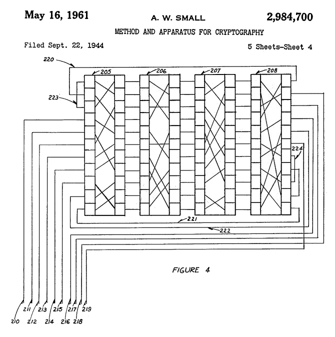 The ASA applied a
new cryptographic
principle called re-entry or
re-flexing, with 36-pin rotors. The idea was to take
parts of the cipher output, re-enter the output back into
the enciphering process, and re-encipher it again.
Cryptanalyst Albert W. Small
The ASA applied a
new cryptographic
principle called re-entry or
re-flexing, with 36-pin rotors. The idea was to take
parts of the cipher output, re-enter the output back into
the enciphering process, and re-encipher it again.
Cryptanalyst Albert W. Small ![]() conceived the
system in 1940 and filed it for patent in 1944. However,
his patent was placed under Patent Office Secrecy Order,
and would cause a patent conflict in 1957.
conceived the
system in 1940 and filed it for patent in 1944. However,
his patent was placed under Patent Office Secrecy Order,
and would cause a patent conflict in 1957.
The rotors were a further development of the early World War II types. The so-called Blue Rotor, used until the late 1950s, was a fairly large Hebern-type 26-pin rotor, simple and rugged. The regular rewiring of those rotors, required for security reasons, was quite complicated. A modified version of the Blue Rotor, called White Rotor, carried an alphabet ring and notch ring.
The U.S. Navy also developed a smaller Hebern-type 26-pin rotor, called Yellow Rotor, for its successor to the CCM. There was also a study on the use of printed rotors, with the circuits etched onto the rotor body. That project ended in 1953 and was ultimately abandoned.
The Armed Forces Security Agency (AFSA) was created in 1949 as the first American central cryptologic organization. One of its goals was to provide standardization of secure communications devices and determine a general policy for crypto equipment. The research, conducted by the ASA, was transferred to the AFSA in December 1949. The MX-507 was renamed AFSAM-7, which stands for Armed Forces Security Agency Machine No 7.
After a series of cryptologic studies, already initiated in 1946, AFSA decided to use the 36-pin Red Rotor, with rotatable alphabet ring and notch ring, for both the offline AFSAM-7 and AFSAM-9 teletype encryption. However, the Red Rotor had two major problems: tolerance issues with the plastic molding process, and contact problems. The rotors used beryllium copper contacts, from which particles wore off and turned into abrasive non-conductive copper oxide. This worsened the wear even more and also caused contact problems.
* From 1946 on, external contractors studied the problems with the Red Rotors. Tests with 200 contact materials found none better than beryllium copper, and the plastic compound was still the best suitable. After more modifications and improvements, the Red Rotor was accepted, but contact problems persisted. It is important to note that the beryllium copper dust particles from the rotor contacts are toxic and could cause the lung disease berylliosis. Inhaling these particles should be strictly avoided.
* After ten years of research, costing $1,250,000 (equivalent to $14,598,851 in 2025 currency), they arrived at the Orange Rotor. One of the improvements was the rotatable alphabet ring, easily set by depressing and rotating it, without having to remove it from the rotor. Production of the Orange Rotor started in 1956. This rotor became the standard 36-pin rotor, also for the KL-47B and KW-9. The development and production of the rotors involved Molded Insulation Company, Minneapolis-Honeywell Regulator Company, and American Phenolic Corporation (Amphenol).
In April 1949, the United States and its allies formed the North Atlantic Treaty Organization (NATO), and deteriorating relations with the Soviet Union resulted in a grim Cold War. Secure communications between the NATO members were an important part of making a front against the USSR. An additional challenge faced by the AFSA was to design for themselves a machine that could also be distributed among their NATO allies without disclosing vital secret crypto technology that might end up in Soviet hands.
Given the size of NATO, it was more than likely that this machine, or its specifications, would eventually reach Russian soil. The design had to withstand any possible cryptanalytic attack by the Soviet codebreakers, even when the technical details of the machine were disclosed. The security of the machine had to depend solely on the secrecy of the key settings, in keeping with Kerckhoffs’ well-known principle of cryptography.
In September 1950, the AFSA demonstrated an engineering model. The final design used eight 36-pin rotors, a re-entry of ten rotor signals, and a most complex irregular stepping of the rotors, electrically controlled by notch rings on the rotors. The problems with the printer timing and the letters/figures shift system, were solved by a clever design with electron tubes, making the AFSAM-7 the first tactical cipher machine ever to use electronics.
The AFSAM-7 was approved, and the Army could build prototype models. By December 1950, the Army declared the AFSAM-7 ready for production. The machine would become the first standard crypto machine in the U.S. Armed Forces. The cryptosystem was designated POLLUX. Contractors were selected, and operational and maintenance manuals were composed. In February 1951, contracts were signed to produce 25,000 AFSAM-7s, at a rate of 5,000 per year. The first repair and maintenance course for Army and Air Force personnel was scheduled in September 1951. However, due to tooling problems and material shortages, delivery of the AFSAM-7 was first delayed to June 1952 and then delayed again to January 1953.
In 1951, the BRUTUS crypto principle was proposed as replacement for the CCM's outdated AJAX crypto principle. The BRUTUS rotor stepping maze controlled the irregular movement of the rotors, with rotors 2 and 6 rotating in opposite direction, differing from the POLLUX stepping logic. BRUTUS used seven 26-pin rotors from a set of ten, with removable cams and alphabet rings. The number of notches on the notch pattern had to be 7, 9, 11, 15, 17 or 19 (co-primes). Meanwhile, the Navy had been developing its own machine, initially named Portable Cipher Machine (PCM), and later renamed AFSAM-47. They had already adopted the BRUTUS crypto principle for their AFSAM-47, but production, planned for late 1950, was already delayed.
The upper-case system on the British TYPEX cipher machine was non-standard, making a combined U.S./U.K. system impossible until TYPEX was replaced. The CCM Replacement's Working Party suggested a system for combined use, to achieve compatibility between AFSAM-7, AFSAM-47, the British SINGLET, and other U.K and U.S. machines. This comprised the Space key to piggyback on letter Z, switch to figures on J and switch to letters on V.
However, the design of
the AFSAM-47 used the eight upper-case characters
- ( ) / : ? , . and was only
compatible with the British SINGLET machine.
Neither the limited nor extended upper-case
system could be introduced until the British
stopped using the TYPEX with BRUTUS adaptor. The limited upper-case
system, which included
numerals and space, was eventually adopted for
all combined cipher machines. Until a combined
policy was agreed, all cipher machines, designed
for U.S./U.K. use, were required to include at
least the limited upper-case system.
In October 1951, AFSA announced two types of operation: the AFSAM-7 traffic for high-level communications was designated ADONIS, while traffic for the Army and Air Force was designated POLLUX. The differences between the two cryptosystems were the rotor sets, and the Message Rotor Alignment procedure at the start of each individual message. In 1952, the British services wanted to use the BRUTUS crypto principle to replace the CCM, as agreed in 1951. However, analysis showed that initial and long-term costs of meeting NATO requirements, including parts and rotors, were less expensive for ADONIS with 36-pin rotors, compared to BRUTUS. Plans were made for a phased introduction of the ADONIS principle in combined machines by January 1955. ADONIS equipment would be made available to the U.K. until they could produce their own version with ADONIS principle. The final production contract for the AFSAM-7 was signed on February 9, 1952. The U.S. urged to standardize ADONIS with 36-pin Red Rotors, as these supported the re-entry principle, which is impossible with 26-pin rotors. ADONIS also avoided the use of rotor cage adaptors, ensuring compatibility with other combined machines. AFSA's successor, the newly formed NSA, also preferred ADONIS because the AFSAM-9 online teletype encryption machine with nine 36-pin rotors, later renamed TSEC/KW-9, was also in development. As it turned out, the TSEC/KW-9 pushed the speed of electromechanical encryption to its limit and suffered from frequent synchronization loss. |
|

In December 1952, the U.S. Office of Communications Security Conference discussed the replacement of the CCM. Participants included the U.S. Army, Navy, Air Force, and cryptologists William Friedman and Albert Small. By then, the British were using the early POLLUX procedure. Although technically identical, ADONIS conveyed the Message Indicator (i.e., rotor start positions) in encrypted form to the receiver whereas the earlier POLLUX procedure used a less secure method in clear. Friedman raised the question whether they should say nothing to the British about POLLUX being inadequate and ADONIS more secure.
Meanwhile, the production of the Navy AFSAM-47 kept delaying and the security of BRUTUS was questioned. One proposal was to improve the security of BRUTUS with its 26-pin rotors by adding a plugboard. Although this could make it more secure than ADONIS, the AFSAM-7 had already been developed and in production by the Burroughs corporation. The BRUTUS-based Navy AFSAM-47, manufactured by Teletype Corporation and subcontractors, was two years behind. The U.S. Army and Air Force preferred the AFSAM-7, and it could be made available for combined and NATO use by early 1955. The use of a plugboard for the AFSAM-7 was also briefly discussed, but William Friedman argued that operators strongly opposed the idea because setting a plugboard was error prone and also created problems when a message from the previous day would arrive.
In the long term, the AFSAM-7 with 36-pin rotors was more secure than the Navy AFSAM-47 with 26-pin rotors, as the AFSAM-7 resisted cryptanalysis longer. According to Friedman, cryptologists from both the U.S. and the U.K. agreed against BRUTUS for the AFSAM-47. Albert Small also preferred the ADONIS principle, but the U.S. Navy insisted on continuing production of the AFSAM-47 using the BRUTUS principle. Although the British preferred BRUTUS, it was practicality, production costs and quick replacement that prevailed.
It was officially agreed that the SIGABA CCM machine, which used the less secure AJAX principle, urgently required replacement, as all cryptanalytic attacks, effective agianst AJAX also worked on the CSP 2200, a modified SIGABA ECM Mark II. Friedman made it clear that ADONIS and AFSAM-7 were the solution to the CCM problem. Meanwhile, Navy tests on the AFSAM-47B, a modified AFSAM47 with 36-pin rotors, compatible with ADONIS, were underway and had already performed 100 hours on the KL-47 printer without error. However, any production of the AFSAM-47B was at least two years behind that of the AFSAM-47.
The Joint Chiefs of Staff believed that replacing the CCM by a machine with the BRUTUS principle should be suspended until service tests of the AFSAM-7 were completed. However, the Navy insisted on retaining the AFSAM-47 with BRUTUS and wait to see whether the AFSAM-7 ADONIS tests and production would succeed or fail, before redesigning their own AFSAM-47 into the AFSAM-47B with 36-pin rotors.
By November 1953, the British delegation of the COMSEC Conference, which assessed the security of cryptographic equipment, did not favor POLLUX, because using Message Indicators in clear posed risks of in-depth messages and recovery of the key settings, certainly with high traffic volumes. In contrast, ADONIS was considered secure at all classification levels for at least ten years, when proper operating standards were maintained. U.S. cryptologists even considered the machine secure for the next twenty years. In contrast, the British considered the AFSAM-47 with BRUTUS principle only secure for the next five years. They also recommended to replace the British CCM as soon as possible, since it was expeted to become insecure within three years. The TYPEX II and Typex Mk 22 remained secure for the next five years.
The AFSAM-7, favored by
the NSA, eventually proved successful, and the
ADONIS principle was also chosen for the Navy
AFSAM-47B. The NSA introduced the AFSAM-7 into
the U.S. Armed Forces, and a smaller number was
also purchased by the Federal Bureau of
Investigation (FBI) and the Central Intelligence
Agency (CIA). The machine resisted any known
cryptanalytic attack at the moment of its
release. In 1955, the AFSAM-7 was renamed
TSEC/KL-7, according to the new nomenclature for
crypto equipment.
An ancillary Baudot paper tape reader called TSEC/HL-1 was developed for the KL-7 to enable directly reading and processing 5-bit level punched tape, as produced by standard teleprinters. This optional feature required the removal of the KL-7 keyboard and installation of the KLX-7/TSEC keyboard adaptor between keyboard and chassis. The AFSAM-47B was renamed TSEC/KL-47 and was compatible with the KL-7. Individual components of the KL-7 and KL-47 were manufactured by several different U.S. government contractors. After final assembly at various locations, the machines became the property of the NSA, and the ASA distributed them to the U.S. Armed Forces. Although cryptographically compatible with the KL-7, the KL-47 retained an extended upper-case system with punctuations, while the KL-7 had a limited upper-case system with numerals only. Therefore, sending messages from a KL-47 to a KL-7 required spelling out the punctuation marks, or omitting them, to avoid decryption errors. In 1957, Boris Hagelin, engineer and founder of the Swiss firm
Crypto AG, told NSA
cryptologist William Friedman
The issue of conflicting patents had
to be resolved. The NSA feared that sensitive
information might be disclosed, and preferred
that Albert Small's pending application remained
classified if he would not acquire legal claims
for compensation. Another option was to release
only unclassified portions of the patents.
Eventually, the conflict was solved, and Albert
Small's Patent 2.984.700 |
|
TEMPEST Issues TEMPEST, the procedures and techniques to shield devices against eavesdropping on unintentionally emitted signals, was in its early stages of research when the KL-7 was being developed. Although Bell engineers recognized the risk of unwanted stray signals as early as 1943, initial attempts to reduce these signals were limited to filters on the power supply and shielding as much as possible. The first breakthrough came in 1956 with the introduction of low voltage circuits with transistors.However, this occurred four years after the introduction of the KL-7, and the first extensive TEMPEST regulations were only drafted in 1958. De KL-7 has a radio interference filter between the external power supply and its electronics, but some electrical contacts and coils could still be a source of unwanted signals. The NSA conducted a study in 1955 to determine whether the coil of the printer magnet, which activates the print hammer, emitted signals that could be exploited. The print coil signals were detectable up to 25 feet from the machine. Analysis of recorded signals
during decipherment of a KL-7 message showed
that, by measuring the interval between the
intercepted pulses of the print magnet, and
knowing the order of the letters on the print
drum, enabled the recovery of the plain text.
Variations in motor speed
between pulses could complicate measurement of
the intervals, but other signals, radiated at the
same distance, could determine the change of
motor speed, making recovery of the plain text
much easier. They also found a correlation
between the number of rotors that stepped and
print drum speed deviations. See also NSA radiation study KL-7 The KL-7 remained in use without additional technical changes to reduce unwanted signals, but the 1958 TEMPEST regulations undoubtedly advised operating the machine at fixed or tactical locations were eavesdropping at close range was unlikely. Nevertheless, even at secure locations, unwanted signals could unexpectedly piggyback on other equipment and enable eavesdropping from far greater distances, as you can read on our TEMPEST page. |
|

The KL-7 in Service
The KL-7 was initially intended only for use by the U.S. Army, Air Force, Navy, FBI and CIA. At the 1953 Communications Security Conference in London, the NSA proposed to share the ADONIS crypto-principle with their NATO allies. The goal was to improve communications security and interoperability, and replace the less secure Combined Cipher Machine (CCM) with the AFSAM-7.
U.S. ARMY |
U.S. AIR FORCE |
U.S. NAVY |
FBI |
CIA |
NATO |
Between 1951 and 1954, the Army Security Agency (ASA) procured 6,547 units, intended to replace the less secure M-209. The FBI ordered 120 AFSAM-7s, 120 Office Cases at $100 each, 120 additional AFSAM-207 Cipher Units (i.e., KLK-7/TSEC) at $50 each, 250 sets of Rotors (two per machine to enable a swift daily key change), five spare AFSAM-107 Stepping Units (i.e., KLA-7/TSEC), five spare AC Power Converters at $25 each, paper tape and ink ribbons. The order totaled $258,900. However, by 1953, the cost of the FBI order had risen to $299,232 (equivalent to $3,560,199 in 2025) due to rising production costs.
ASA initially received 650 AFSAM-7s, including 120 for the FBI. These were gradually issued, two per FBI office. Meanwhile, the twenty FBI offices with the highest message volumes already received AFSAM-7s on loan from the NSA, which also trained FBI personnel in operating the AFSAM-7. The CIA received its first four AFSAM-7s for local testing in 1954, but field use only started the following year.
By 1954, all FBI offices, Quantico, the
White House Signal
Detachment (WHSD)![]() , the Seat of Government and President Dwight
Eisenhower's Air Force One were equipped with the
AFSAM-7. However, many AFSAM-7s from early production
runs suffered from technical deficiencies. In April 1954,
the NSA director received a list of deficiencies, noted
by the Chief Army Field Forces during testing.
, the Seat of Government and President Dwight
Eisenhower's Air Force One were equipped with the
AFSAM-7. However, many AFSAM-7s from early production
runs suffered from technical deficiencies. In April 1954,
the NSA director received a list of deficiencies, noted
by the Chief Army Field Forces during testing.
To meet performance standards, the ASA requested modifications to 2339 AFSAM-7s from the 1st, 2nd and 3rd production runs, at the time at storage facilities. These units were returned the following month to the Burroughs Corporation. Opon arrivel of the second shipment at the ASA, it was discovered that 615 from the 1400 already delivered AFSAM-7s required modifications. As a result, machines already deployed to the White House, ASA Europe, and ASA Pacific had to be replaced by modified versions.
The U.S. Joint Chiefs of Staff approved the use of the AFSAM-7 by NATO in 1954. The plan called for its introduction at medium and high NATO levels by mid-1956. The NSA recognized that the AFSAM-7, or reproductions using the same cryptographic principle, might eventually enter non-military use in NATO countries, or even fall into Soviet hands. Nevertheless, the NSA was confident the AFSAM-7 was secure against Soviet attempts to decrypt the messages, even if its cryptographic principles and specifications were compromised. The machine was therefore certified for handling Top Secret messages.
Meanwhile, the new British BID/60 SINGLET crypto machine was developed with the same crypto principle as the AFSAM-7, intended to replace the aging CCM (LUCIFER), the British CCM-Typex, interoperable with the American CCM/SIGABA. The British SINGLET closely resembled the AFSAM-7 and used identical rotors, but was not expected to enter production before 1960. In 1954, the U.S. decided to allocate 3,500 AFSAM-7 units to the United Kingdom, and 3,000 units to other NATO countries. These machines were on loan and remained property of the NSA.
In early 1955, the Standing Group of the North Atlantic Military Committee (NAMC), which provided policy guidance, decided to supply the AFSAM-7 to the Supreme Allied Commander Europe (SACEUR) for distribution to all NATO members. Target date to replace the CCM with the AFSAM-7 was set for 1 July 1956. In the meantime, the AFSAM 7 was renamed TSEC/KL 7. In 1955, the U.S. Army Security Agency Europe assigned two military instructors to NATO, to assist in training personnel, designated to repair and maintain the KL-7. Those who attended the maintenance school had to be qualified as teletypewriter mechanics and have the proper security clearances. Basic knowledge of electronics was also desirable.
 HMS Eagle R05 aircraft carrier during NATO exercise info Photo Royal Navy MOD Copyright Crown OGL |
* In September 1955, the NAMC issued an allocation list for KL-7s. The then-current allocation quantities were for Belgium 156, Denmark 158 (including Greenland and Faeroes), France 711 (including the Commander Biscay Atlantic sub-area and the Commander Moroccan Atlantic sub-area), Greece 200, Italy 603, Luxembourg 15, Netherlands 239, Norway 169, Portugal 168 (including the Commander Continental Portugal and the Island Commanders of Azores and Madeira). Each country's Ministry of Defense Army, Navy and Air departments received four KL-7s each, and the Supreme Commanders 12 KL-7s.
Within the Allied Headquarters, the HQ
Commanders in Chief received 12 KL-7s. The Allied Land
Commands, Allied Army Groups and Tactical Air Forces, and
Armies and Tactical Air Forces 8 KL-7s each. The Army
Corps and Air Divisions received 6 KL-7s, The Army
Division, Air Force Escadres, and Wing Groups 3 KL-7s.
The independent brigades 2, National District Commands 2,
major fleet Bases 4, Island Commands 3, Patrol Force
Commanders and Flag Officers 2 each, Naval and Maritime
Air Bases 3. Ocean-going aircraft carriers, battleships
and cruisers 2 each, destroyers, destroyer escortes,
submarines, and Patrol Coastal boats 1 each. Temporary or
alternative Naval or Maritime Air bases received 2 KL-7s.
See Allocations 1955 ![]() .
.
Note that 3,500 units had already been
assigned to the U.K. in 1954. In the following years,
more KL-7s were allocated to additional countries and
military echelons, with the 1965 allocations as the last
known. See Allocations 1965 ![]() .
.
In 1956, NATO decided to procure the HL-1 tape reader and KLX-7/TSEC keyboard adaptor to handle the increasing volume of encrypted traffic. The NATO members were required to determine their required stocks of KL-7 spare parts and, could also order a kit with basic spare parts at the price of $150 per machine. The kits and spare parts were gradually delivered between 1957 and 1960.
Also in 1956, CIA's Operations and Training Division planned to employ the AFSAM-7 for mobile message centers. Noise issues were resolved with a soundproof container, and a keyboard adaptor became available in 1957. That same year, CIA O&T personnel visited the NSA to observe the HL-1 tape reader, which could process perforated tapes. The HL-1 was later installed on loan at the CIA Signal Center.
In 1957, NATO agreed to adopt the KL-7 for second-level and first-level communications with ADONIS key lists, replacing Typex (SIMPLEX) traffic that used the Typex II with SIMPLEX pads. This agreement also comprised each NATO member's Ministry of Defense and Foreign Affairs, their embassies in Paris and Washington, and their National Military Representative in Washington. In 1958, KL-7 deployment was further extended to minesweepers, fast patrol boats, and long-range maritime aircraft.
| NATO MEMBER STATES IN 1957 | OUTSIDE NATO |
Besides the United States, the KL-7 was used by its NATO allies Australia, Belgium, Canada, Denmark, England, France, Federal Republic of Germany (former West Germany), Greece, Italy, Luxembourg, Netherlands, Norway, New Zealand, Portugal, and Turkey. Outside NATO the KL-7 was also on loan to South Korea, South Vietnam and Taiwan.
Some geopolitical info on the Asian countries: South Vietnam, officially the Republic of Vietnam (RVN), existed from 1955 until the North Vietnamese victory in 1975 and unification into the current Socialist Republic of Vietnam (SRV) in 1976. South Korea was established in 1948, following the division of the Korean peninsula into two states along the 38th parallel, with the U.S.-backed South Korea, officially the Republic of Korea (ROK), and the Soviet-backed North Korea, officially the Democratic People's Republic of Korea (DPRK). The Republic of China (ROC), often called Nationalist China, was founded in 1912. Following the 1949 civil war and Chinese communist victory, the Kuomintang retreated to Taiwan and retained the name Republic of China. Their status is disputed by the mainland People's Republic of China (PRC) to this day.
In 1958, the price per KL-7 totaled $1458. The set comprised the KLB-7 base at $814, KLA-7 stepping unit $328, KLK-7 cipher unit $80, CE87054 Carrying Case $161, CE87066 AC Power Converter $75 and a set of rotors $100. A complete KL-7 would cost $16,025 when converted into 2025 currency.
The extended use of the KL-7 was discussed, and NATO member Canada pointed out that the KL-7 had not yet achieved 100% reliability due to problems with the pulse generator and proposed a book cipher as essentialback-up. The KL-7 was also used aboard NATO submarines. In 1959, they approved the Basic Submarine Code as back-up system for the KL-7. The code, in itself not secure enough, was used in conjunction with one-time letter pads. In December 1959, NATO authorized the use of KL-7 ADONIS for first level military and diplomatic traffic. By 1966, some 25,000 KL-7s had been produced for the U.S. and its allies.
When France left NATO's military structure in 1966, NATO required a separate cryptosystem to exclude France from its most sensitive communications. Initially, two new KL-7 ADONIS key lists and a new set of rotors with other internal wiring were introduced. NATO did continue to distribute COSMIC TOP SECRET key lists to France but introduced separate key lists for the ohter nato members, from which the French were excluded. The KL-7 key lists for General Small Ships, the Maritime Patrol Aircraft, Atlantic Channel North Sea and Baltic Area remained available to France.
For transport,
accessories and operating, the KL-7 had three
types of casings.
The KLB-7 Base with all electronics was not classified. The KLA-7 Rotor Stepping Unit with actuator switches and wiring was classified CONFIDENTIAL. The KLK-7 Cipher Unit was also CONFIDENTIAL. The maintenance rotors were CONFIDENTIAL, the operational POLLUX rotors CONFIDENTIAL and ADONIS rotors SECRET. Usually, two Cipher Units were available for each KL-7, one with the current day key settings and one with the previous day settings. The KL-7 also came with an operator maintenance kit in a small square metal box, containing a few tools, a cleaning block to clean keyboard and rotor contacts, contact cleaner and lubricant, a brush and bristle, spare electron tubes and neon bulb for the Shift indication. In the audio on the right, when the KL-7 is turned on, the DC motor slowly takes speed, and the reduction gears produce the characteristic high-pitched noise. The advancing rotors also produce their typical sound. On the audio you hear at 0:00 the startup, 0:05 manually advance one rotor with Set Key button step by step and at 0:07 continuously, 0:11 typing plain text, 0:17 switch to cipher, 0:20 encipher, 0:25 switch off the KL-7. |
|
The
KL-7 and KL-47 rotors were
rewired regularly. Some on a yearly basis on
national or NATO level, and some, often referred
to as NSA rotors, were to be sent directly to the
NSA and rewired by NSA personnel only. It was
strictly forbidden to operators, and even to
maintenance technicians with crypto clearance for
KL-7, to check out the internal wiring of the
rotors. |
|

* The technicians were not allowed to test
the rotors pin-to-pin. They were instructed to
place a defective rotor on a large conductive
plate that made contact with all rotor pins at
once, and check the connection on each pin at the
other side with an Ohm meter. This allowed the
technician to detect a broken wire without
revealing its corresponding pin on the other side
of the rotor
Despite its extensive use, the KL-7 was not universally popular. During start-up, the electron tubes need 16 seconds to heat up before typing on the keyboard is possible, as the printer timing is controlled by the electronics. The machine also produces a significant acoustic signature, and the motor gears produce a high-pitched noise. The KL-7 was also notorious for its regular contact problems, caused by the keyboard and rotors. The operator often had to push firmly on the keys to get the machine cycling, not allowing him to get any speed. Dirty contacts could cause the machine to halt, the so-called dead-rove. To prevent or solve contact problems, the rotors and keyboard contacts had to be cleaned regularly and meticulously. In Plain mode, there are only two contact points from any key to a pulse coil. In Encipher or Decipher mode, the signal passes 13 contact points, and two additional contact points when using the FIG or LET key. Moreover, each pass through the re-entry wires adds another 9 additional contact points in the rotors. To use all keys, a total of 472 contacts must work flawlessly to prevent the notorious dead-rove. More about the signal path and contact problems in the Selector section. |
 Operator typing on KL-7 with HL-1 tape reader to his left. Photo NSA - COMSEC Analysis SE Asia 1970. Notice |
There were incidents where a KL-7
or KL-47 was compromised. One well-known incident was the
seizure of USS Pueblo by
North Korea in 1968![]() . Officially, the ship was an AGER-2 (Auxiliary
General Environmental Research). In reality, the ship was
stuffed with SIGINT (Signals Intelligence) and ELINT
(Electronic Intelligence) equipment to eavesdrop on North
Korean and Soviet communications and technical signals.
When the North Koreans attacked and boarded the ship, the
U.S. Navy immediately stopped all communications with the
KL-47 until the NSA had distributed new key lists. The
machine itself was designed to resist cryptanalysis, even
when all technical specifications were known to the
adversary, or a complete KL-47 was captured. What they
didn’t know at the time, was that some KL-47 key lists were
already compromised.
. Officially, the ship was an AGER-2 (Auxiliary
General Environmental Research). In reality, the ship was
stuffed with SIGINT (Signals Intelligence) and ELINT
(Electronic Intelligence) equipment to eavesdrop on North
Korean and Soviet communications and technical signals.
When the North Koreans attacked and boarded the ship, the
U.S. Navy immediately stopped all communications with the
KL-47 until the NSA had distributed new key lists. The
machine itself was designed to resist cryptanalysis, even
when all technical specifications were known to the
adversary, or a complete KL-47 was captured. What they
didn’t know at the time, was that some KL-47 key lists were
already compromised.
During the Vietnam War,
KL-7’s were loaned to the Army of the
Republic of Vietnam (ARVN). In 1965, the 101st US
ASA Security Detachment, operating under cover
designator 7th Radio Research Unit, was based in
Saigon (today Ho Chi Minh City).
The 7th RRU conducted Signal Security
(SIGSEC) and also performed the cryptographic
security analysis of the ARVN's use of the KL-7 The U.S. forces in Vietnam used
the KL-7 from division down to company level.
However, the 101st ASA Detachment COMSEC analysis They didn't use the KL-7 for intra-battalion and lower echelon communications, and used manual systems instead, often cryptographically less secure, or even plain unencrypted messages over radio. During the course of the Vietnam war, and after the withdrawal of most U.S. troops in 1973 and the subsequent defeat of the ARVN in 1975, various types of crypto equipment, including some KL-7s, fell into NVA hands. One of those machines, a KL-7 belonging to a U.S. Marine unit, was handed over to the Russians who sent it to the Soviet Socialist Republic Poland for analysis. After the dissolution of the Soviet Union, Polish officials handed over that KL-7 to the NSA, and the machine is now in NSA's National Cryptologic Museum collection. |
 KL-7 captured by NVA and returned to NSA in 2000. Left of the Carrying Case you see the KLX-7 keyboard adaptor NSA - National Cryptologic Museum |
* In Vietnam, the COMSEC support for the KL-7 was
organized by the ASA, located at Tan Son Nhut Air Base in
Saigon. The Special COMSEC Support Unit at the Air Base
provided crypto maintenance down to component level.
Their mission, among others, was to support the crypto
unit of the ARVN. In 1971, the KL-7 was issued to the
ARVN, and they were trained to perform basic maintenance
and operation of the machine. They also received the
Hagelin licensed M-209B and some other Crypto AG units
with keyboards. More details in KL-7 in Vietnam and U.S. Tech Support ![]() .
.
*
During the Cold War, NATO troops from the United States,
the United Kingdom, France, Belgium, Canada, and the
Netherlands were stationed in West Germany and signals
units from the participating countries, including the
German Bundeswehr, provided secure communications to
NATO. From the early 1960s, British signal personnel
supported the mobile communications of the Northern Army
Group, and NATO's Joint Headquarters in Rheindahlen. They
used one-time tape mixers and later also the KL-7, often
superenciphered with one-time tapes. The full story in KL-7 at NATO in West Germany ![]() .
.
Although the KL-7 was intended only for
use by the U.S. military, its NATO allies and certain
state departments, there were some instances in which
civilians operated the machine. One example was during
the 1982 Falklands War. Within days, the British Navy had
to deploy a huge naval task force across the South
Atlantic. They quickly chartered merchant ships to
support the operations. One of them was the Eburna tanker
that carried fuel oil, diesel, and aviation fuel to
transfer fuel at sea. The civil radio officer had no
experience with naval communications or cryptosystems and
had to learn the basics of cryptography and operating the
KL-7 within a very short time. More in KL-7 on Merchant Ships during the Falklands War ![]() .
.
Advances in technology and the introduction of miniature electronic components increased the computational power to support cryptanalysis tremendously. As a result, the KL-7 was no longer considered secure enough by the mid-1960s, and vital message traffic, enciphered with the KL-7, was often superenciphered (i.e. double enciphered) on other systems. From the 1970s on, the KW-26 and KW-37 online cipher equipment largely replaced the KL-7. Some machines stayed in service, mostly as back-up, and retired in the mid 1980s.
The KL-7 was unclassified but the cipher unit wiring, the entry plates and the stepping circuitry were confidential. After their service time, most KL-7 and KL-47 machines and their rotors were recalled. The surviving KL-7’s were carefully stripped from their stepping mechanism wiring and rotor entry wiring, commonly denoted as ‘sanitized’. The fully electronic KL-51 RACE offline cipher machine could be regarded as the successor of the KL-7.
TSEC/KL-7
Timeline

The timeline above shows the development from MX-507 project to AFSAM-7 and TSEC/KL-7. The ASA developed, procured, and distributed the machines. From 1949 onward, the AFSA and later its successor, the NSA, was responsible for communications security. Although the AFSAM-7 existed on paper in 1949, it took two years from the 1950 engineering model to the actual start of production in 1952, with deliveries to the Armed Forces only beginnng in early 1953. The POLLUX procedure for low-level message traffic was adopted in 1950 and the more secure ADONIS procedure for high-level message traffic was added in 1951. Owing to persistent problems, the Red Rotors were replaced by the Orange Rotors in 1956.
Although the NSA succeeded the AFSA in 1952, the machine's name did not change to TSEC/KL-7 until 1955. Machines produced from 1955 onward carried the name TSEC/KL-7, while earlier production runs were gradually retrofitted with the updated name labels. The exact dates of the KL-7's final decommissioning are unknown, as they were gradually recalled from multiple services and allied countries, with Canada as the last known user until 1983.
The KL-7 is a unique machine in many ways. It was the first mulinational crypto machine, developed under one centralized cryptologic organization and introduced as a standard machine in all parts of the armed forces of many allied countries. At that time, the KL-7 used the latest cryptologic techniques and was the first ever cipher machine with electronics, yet its rotor-based design would soon lose the battle against miniaturization of electronics and computational power. The KL-7 proved to be one of the last purebred electromechanical cipher machines.
Many operators cursed the machine for its quirky keyboard and regular contact problems. They welcomed its electronic successors, but today they speak with sentiment about that wonderful machine and even vividly remember the typical sound of its stepping rotors. Maybe because of the era in which the KL-7 and the operators gave their best, or because the KL-7 served all over the world, collecting secrets and memories about the Cold War, companionship, and even exciting stories about treason and espionage, because this was not the end of the KL-7 story...
Major Security Breaches
In 1974, a highly sensitive and well-placed source told the FBI that the Soviet military intelligence directorate GRU had an agent codenamed "Greenwood", who was an American from the U.S. military, previously stationed in France and Vietnam. The FBI launched counterintelligence operation codenamed "Hookshot", and the Army Intelligence and Security Command (INSCOM) narrowed the search to former U.S. Army Signals Warrant Officer Joseph Helmich (1937–2002). From 1958, Helmich held a Top Secret security clearance. He served in 1963 as a crypto custodian in France, and from 1964 to 1965 in Vietnam with crypto clearance in a supply unit. In 1966 he was stationed at Fort Gordon, Georgia, but resigned from the Army after his security clearance was revoked. Since Helmich fit the profile perfectly, the FBI launched an intensive surveillance investigation.
Facing financial problems, Helmich contacted the Soviet Embassy in Paris in 1963 and received $131,000 in exchange for technical information on the KL-7, which at the time was the most widely used cipher machine in the U.S. military. After returning to the United States, Helmich continued to provide KL-7 key lists to the Soviets until 1966, enabling them to decrypt KL-7 messages from U.S. troops and Military Intelligence units in Vietnam. Although suspicions arose as early as 1964, since his wealth did not match his pay grade, it was only during the FBI surveillance in early 1980 that they observed him visiting the Soviet Embassy in Canada to make contact with the KGB. After extensive interrogations, Helmich eventually confessed in 1981 and was sentenced to life imprisonment.
In 1985, the FBI received a tip from the ex-wife of John Anthony Walker (1937–2014), a retired U.S. Navy communications specialist with a Top Secret Crypto clearance. The FBI observed Walker dropping a grocery bag alongside a road north of Washington, D.C. The bag contained 129 copies of stolen secret U.S. Navy documents. At the same moment, a Soviet KGB agent left a grocery bag containing $200,000 a few miles away, a classic espionage tradecraft dead drop to covertly exchange documents and money without meeting face-to-face. John Walker was arrested the following night in a motel. The subsequent investigation sent shockwaves through the military intelligence community.
In 1967, Chief Warrant Officer John Walker simply walked into the Soviet Embassy in Washington, D.C. with a KL-47 key list, offering to sell secret U.S. Navy documents for cash. This marked the start of a spying career that lasted 18 years. In 1973, John Walker recruited his friend Jerry Whitworth (1939–), who was also a U.S. Navy communications specialist. Walker left the Navy in 1976 and recruited in 1984 his brother Arthur Walker (1934–2014), a retired U.S. Navy officer who worked for a Department of Defense contractor. Walker also recruited his son Michael (1954–), who had enlisted in the Navy. They later became known as the Walker spy ring.
During a search of Walker's home after his arrest, the FBI discovered a special device provided by the KGB and designed to read the internal wiring of the KL-47 rotors. During interrogations, Walker also admitted handing over complete technical maintenance manuals to the Soviets, allowing them to reconstruct a fully operational KL-47, cryptographically identical to the KL-7. John Walker, Arthur Walker, and Jerry Whitworth were sentenced to life imprisonment. Michael Walker, who played a minor role in the spy case, was released in 2000.
The importance Soviet Intelligence placed on the KL-7 and KL-47 key lists, despite already possessing full technical details of these machines, suggests they were either unable to break the message traffic purely by cryptanalysis, or they lacked sufficient computing power to decipher and exploit the messages within a practical timeframe during the 1960s.
TSEC/KL-7 Simulator
 You can download a realistic simulation of the
TSEC/KL-7 on this website. This simulator is based on the
most recent information and developed in collaboration
with Crypto Museum
You can download a realistic simulation of the
TSEC/KL-7 on this website. This simulator is based on the
most recent information and developed in collaboration
with Crypto Museum![]() . The simulator
operates in exactly the same way as the real machine.
With most surviving KL-7s sanitized, this simulator is
the only remaining way to actually work with this
beautiful machine and serves to keep this machine and its
history alive. The simulator has an extensive 20-page
manual that includes the use of the simulator, the
technical and historical details, and some example
messages. Please visit the KL-7 Simulator page to
download the software,
. The simulator
operates in exactly the same way as the real machine.
With most surviving KL-7s sanitized, this simulator is
the only remaining way to actually work with this
beautiful machine and serves to keep this machine and its
history alive. The simulator has an extensive 20-page
manual that includes the use of the simulator, the
technical and historical details, and some example
messages. Please visit the KL-7 Simulator page to
download the software,
More on this Website and the SIGINT Chatter blog
- The Origin of TEMPEST Stray electromagnetic pulses and the risks for communications security.
- Operation Tinker Bell Decrypt a series of KL-7 messages to uncover a Cold War spy case.
- USS Pueblo
Incident
 The 1968 capture of a U.S. SIGINT ship
by North Korea.
The 1968 capture of a U.S. SIGINT ship
by North Korea. - Joseph Helmich
– The KL-7 for Cash Spy Case The first
major compromise of the KL-7.
- Chief warrant
officer John Walker He sold
KL-47 key lists and internal wiring rotors to the
Soviets.
- The First Compiled
History of the KL-7 Blog about
research on the KL-7 and composing its history.
References and Documents (onsite and
offsite - open in new tab)
The NSA documents are from their Declassification & Transparency Initiatives, Freedom of Information Act releases (FOIA), the William F. Friedman Collection, and the NSA Historical Releases. Other sources include the National Security Archive, the National Archives, NATO Archives Online, the CIA Reading Room, the governmentattic.org website and the Internet Archive. Additional sources, excerpts or pages are provided with a link to the full document, webpage or website.
- * History of the
TSEC/KL-7 ADONIS & POLLUX
 First extensive history of the KL-7,
the first standard lightweight rotor cipher
machine with electronics, used by the U.S. Armed
Forces, FBI, CIA, NATO, and Asian allies. Dirk
Rijmenants, version 6.1 from 14 May 2026 (refresh
pdf doc).
First extensive history of the KL-7,
the first standard lightweight rotor cipher
machine with electronics, used by the U.S. Armed
Forces, FBI, CIA, NATO, and Asian allies. Dirk
Rijmenants, version 6.1 from 14 May 2026 (refresh
pdf doc).
Technical documents, released by NSA
- NSA - Interim
Operating Instructions for Pollux
Cryptosystems-Joint 1953, Released under AIA, published by Crypto Museum.
- NSA - Repair and
Maintenance Instructions for TSEC/KL-7 1955, FOIA by Bill Neill, published by
Nick England's US Navy Radio
Communications.
- NSA - Plain Text
Radiation Study of the TSEC/KL-7 (AFSAM 7) 1955, study on leaking of information
by the print magnet and rotating drum wheel.
- NSA - Canadian
User Report and POLLUX Interim 1959, first year of operation report
and user manual, released AIA, Jerry Proc's KL-7 page.
- NSA - KL-7 ADONIS
Operating Instructions 1966, KAO-41C/TSEC manual and operating
instructions, released AIA, Jerry Proc's KL-7 page.
- TSEC/KL7 Circuit
Diagram Also available in NSA declassified
Repair and Maintenance Instruction, but better
visible, published by Crypto Museum.
Related technical information
- NSA - US and UK
COMSEC Equipment 1950s US and UK Crypto Equipment, incl.
AFSAM-7, AFSAM-47 & 47B, AFSAM-9 and tech
details.
- NSA - National
COMSEC Materiel Program 1954 charts of AFSAM-7 and AFSAM-47B
development, production and implementation.
- NSA - Nomenclature
Table of Indicators 1954 Nomenclature of Communications
Security Materials (see also full document).
- NSA - Development
Wired Rotors Extract U.S. Communications Security
Post World-War II, pdf p.84-88 (see also full document).
- NSA - KL-7 Lecture
David Boak 1966, Extract History U.S. COMSEC vol I
& vol II, David Boak lectures,
pdf p.29-34 (full document)
- 2D21 Thyratron Gas
Tetrode - data sheet at Tubebooks.org
and see also 2D21 at Valve
Museum.
- 12AX7 Twin Triode
- data sheet at Valve Museum
- JAN 12AX7 Twin Triode 12AX7 with Joint Army-Navy electronics standard for U.S. military supply contracts at TubeDepot website.
- How A Tube Works Mr Carlson's excellent and detailed video about electron tubes (valves) and the principle of triode and tetrode tubes.
Patents and declassification
- U.S. Signal Corps
Patent Board 1940 invention Albert Small has
sufficient military value for application of
patent but should be kept secret.
- Albert Small -
Patent on Re-entry Principle 1944 U.S. Patent 2.984.700 re-entry
principle, filed 1944, issued 1961 after solving
patent conflict.
- Boris Hagelin -
Patent on Re-entry Principle 1953 filed U.S. Patent 2.802.047
re-entry principle, issued in 1957.
- NSA - Request
Declassification Re-entry Patent 1956 report Chief NSA Patent Branch on
Albert Small's request declassification patent.
- NSA - Hagelin
Negotiations - Albert Small Patent 1957 extract Friedman report
conflicting Hagelin patent on re-entry principle
(full document)
- NSA - Sinkov on
Re-entry Patent Conflict 1965 NSA's Abraham Sinkov
recommendations on release of Albert Small's
re-entry patent.
CIA and FBI documents AFSAM-7 and TSEC/KL-7
- FBI - Purchase
AFSAM-7 1951-1955, order of 120 AFSAM-7, office
cases, cipher units, rotor sets, etc. (full document at The Black Vault)
- CIA - Newsletter 1953, delivery first four AFSAM-7 to
CIA for local testing. Use in the field not
before 1954 (CIA reading Room)
- ASA History Vol I 1954, procurement 6547 AFSAM-7 of which
120 for FBI, White House and Air Force One, pdf
p.1-2, p.4-5, (full document)
- FBI - Memorandum
of Conference AG's 1955, J.E. Hoover, AFSAM-7 procured for
all field offices, Quantico and Govt, pdf p3 (full document)
- CIA - Systems
Engineering Branch 1956, AFSAM-7 for Mobile Message
Center, noise issue, keyboard adaptor, pdf p.4,
p.7 (CIA reading Room)
- CIA - Memorandum 1957, Trip to NSA by O&T and
Security Divisions for HL-1 tape reader, one in
loan for Signal Center (CIA Reading Room)
- FBI - Bureau Codes
1960, letters J.E. Hoover on
distribution AFSAM-7/KL-7, key lists FBI offices,
training, pdf p.3, p.5, p.17 (full document)
- CIA HQ Signal
Center 1951-1966, extract AFSAM-7 from history
CIA Headquarters Signal Center Expansion (CIA reading room -
full document)
Reports on sharing the KL-7 with NATO and used crypto principles.
- NSA - Discussion
Disclosure Crypto Principles AFSAM-7 1950, BRUSA conference with William
Friedman, Abraham Sinkov, Albert Small et al.
- US ARMY CoS -
Report COMSEC Conference London 1951, p11-12 details BRUTUS crypto
principle and at p33-35 limited upper-case.
- NSA - Discussion
Replacement CCM 1952, Office of Communications Security
Conference U.S. Army, Air Force, Navy, Friedman,
Small et al.
- US ARMY -
Replacement CCM 1952, U.S. Joint Chiefs ot Staff,
introduction ADONIS principle as new Combined and
NATO cryptosystem.
- AFSA - Attacks on
AJAX 1952, Memo for record, cryptanalytic
attacks on AJAX also work on the CSP 2200
(modified ECM Mark II).
- NSA - Replacement
Combined Cipher Machine (CCM) 1953, Advice to replace CCM by AFSAM-7,
four production models shipped to London.
- NSA - Disclosure
ADONIS (US) Cryptoprinciple to NATO Countries 1953, memorandum sharing AFSAM-7 (KL-7)
ADONIS with NATO countries.
- NSA - UK/US COMSEC
Conference Report 1953, U.S. sharing 3500 AFSAM-7 with
U.K. and 3000 with other NATO countries.
- NSA - UK/US COMSEC
Conference Sub-Committee 1953, Security assessment of
cryptographic equipment in use and under
development.
- NSA - Release
AFSAM-7 to NATO Nations 1954, memorandum release AFSAM-7 to
NATO countries and inevitable spreading crypto
principles.
Documents from NATO Archives Online at https://archives.nato.int. Please consult their guidelines for use, permission and credits.
- NATO - Proposal
Distribution AFSAM-7 1955, Memorandum SACEUR target date to
replace CCM by AFSAM-7 is 1 July 1956 (archive details)
- NATO - Training
Personnel in Operating, Maintenance and Repair
TSEC/KL7 1955, training and required
qualifications (archive details)
- NATO - Provision
TSEC/KL7 Initial Quantities and Allowance 1955, initial national quantities and
proposed allowance per services (archive details)
- NATO -
Cryptographic Arrangements NATO 1956, KL-7, Typex SIMPLEX and Typex
LUCIFER (archive details).
- NATO - Automatic
Use of the TSEC/KL-7 1956, TSEC/HL-1 tape reader and KLX-7
keyboard adaptor (archive details)
- NATO - Policy
Ordering and Maintaining Supply Spare Parts
TSEC/KL-7 1956, ordering parts and stock (archive details)
- NATO - Replacement
First Level Typex-Simplex Channels 1957, KL-7 for first level military and
diplomatic channels (archive details)
- NATO - TSEC/KL-7
Meteorologic Use 1958, use by Minesweeper, Patrol Boat,
Maritime Aircraft, including price KL-7 and parts
(archive details)
- NATO - Extension
Use TSEC/KL-7 for General NATO Communications 1958, KL-7 approved for second level
NATO comms (archive details)
- NATO -
Availability HL-1 and KLX-7 1959, request Federal Republic of
Germany for 38 TSEC/HL-1 and KLX-7/TSEC (archive details)
- NATO - Submarine
Code in Conjunction with One-time Pad as Backup
for KL-7 1959, command to all subs, subs only to
command (archive details)
- NATO - TSEC/KL-7
ADONIS Systems for National Traffic 1959, authorization for national
military and diplomatic traffic (archive details)
- NATO - Allowance
Table for ADONIS Equipment 1965, list of countries and allotted
KL-7 per department and military levels (archive details)
- NATO -
Distribution Cryptomaterial after France leaving
NATO 1967, separate KL-7 key lists for
France when they left NATO (archive details)
- * NATO - Annual
Review Espionage Cases 1980-1981 Joseph Helmich compromise KL-7, page
17-18 (archive details
and full document)
- * NATO - Annual
Review Espionage Cases 1984-1985 Walker Spy Ring compromise KL-47, page
26-27 (archive details
and full document)
Miscellaneous historical documents
- The KL-7 in
Vietnam and U.S. Tech Support Story of Darwin Maring, NCOIC of the
Special COMSEC Support Unit at the Air Base in
Saigon.
- The KL-7 at NATO
in West Germany Story of British Electronics Technician
Mo Davies on OTT Mixers and the TSEC/KL-7 at
NATO.
- The KL-7 on
Merchant Ships during the 1982 Falklands War Story radio officer on the Eburna
tanker that supported the British Naval Task
Force.
- NSA - Cryptologic
Almanac 50th Anniversary Series History of the development of the
AFSAM-7.
- NSA - Working
Against The Tide Vietnam 1965, battle of Ia Drang, use
KL-7 at division down to company level, pdf
p102-104 (full document)
- ASA - Historical
Summary 1965 ASA's 7th Radio Research Unit in
Saigon. Security analysis of South Vietnamese use
of the KL-7 (archive).
- NSA - U.S.
Communications Security Board 1970, proposal KL-7 Brazilian Navy,
KL-7 already in South Korea & Nationalist
China (full document)
- National Archive Records NSA/CSS Timeline with dates establishment U.S. Army cryptologic services SIS, SSA and ASA.
- NSA - Post War
Transition Period ASA 1945 - 1948 transition Signal Security
Agency into Army Security Agency, missions and
equipment.
- Early History of
SIS, AFSA and NSA Creation Signal Intelligence Service,
Armed Forces Security Agency and National
Security Agency.
- Joint Chiefs of
Staff - Memorandum AFSA 1949, JCS memorandum to director of
Armed Forces Security Agency on establishment of
AFSA.
- AFSAC - Directive
of Establishment AFSA 1951, Armed Forces Security Agency
Council, establishment Armed Forces Security
Agency (AFSA).
- History of the Army Security Agency (ASA) The U.S Army signals intelligence branch from 1945 to 1976 (archived).
- The Early History of WHCA White House Communications Agency (WHCA) and White House Signal Detachment (WHSD), John Cross.
- Cryptography - First use KL-7 Description and use KL-7 in the Royal Navy, by Godfrey Dykes, RN Communications Branch Museum/Library.
- Cold War Machine Cryptography Including the KL-7 in the Royal Navy, by Godfrey Dykes, RN Communications Branch Museum/Library.
- FBI - Operation
Hookshot Extracts identification Joseph Helmich
who sold KL-7 tech details and keys to the
Soviets (full documents - 3
pdf)
Important: In the Hookshot docs is Soviet Intelligence Service abbreviated as SIS, not to be confused with British Secret Intelligence Service SIS. - DNI -
Counterintelligence Helmich Extract Joseph Helmich spy case details
and investigation, pdf p269-271 (full document - CI references)
- CIA - Ex-Army
Cryptographer Indicted on Spy Charges Joseph Helmich, declassified part
sanitized copy Washington Post, released CIA
2012.
- CIA - Generals
Testify in Spy Case Generals Westmoreland and Rienzi in
Helmich case, sanitized copy New York Times,
released CIA 2010.
- CIA - Prosecution
in Ex-GI's Spy Trial Paris Saga Joseph Helmich, declassified part
sanitized copy Washington Post, released CIA
2010.
- Life Term Imposed in Espionage Case Joseph Helmich Digitized version of an article from The New York Times, October 17, 1981 (archived).
- DNI -
Counterintelligence John Walker Extract Walker Spy Ring case details
and investigation, pdf p237-240 (full document - CI references)
- NSA -
Cryptographic Damage Assessment USS Pueblo NSA report equipment seized by North
Vietnam, partial destruction KL-47 and its
rotors.
- Analysis of
Security Weaknesses Exploited by CWO John Walker by Laura J. Heat, Maj USA, M.S.,
Georgia Institute of Technology, 2001.
- The Navy's Biggest Betrayal on the U.S. Naval Institute The story of John Walker's spy ring by John Prados, 2010.
- USS Pueblo, John
Walker and KGB Robert Derencin article on John
Walker's treason and the compromised crypto
equipment, 2020.
More about the TSEC/KL-7 and Related
Equipment (offsite - opens in new tab)
- TSEC/KL-7 on Crypto Museum Detailed technical information and many high-quality images.
- TSEC/KL-7 on Crypto Machines Jerry Proc's webpage on the KL-7, with information from various sources and former operators.
- 3D Model of KL-7 at Scetchfab Shashwat Patkar's excellent highly detailed 3D model. See also his KL-7 project on Art Station.
- TSEC/HL-1 Tape Reader Jerry Proc's Baudot punched paper tape reader for KL-7, see also Nick England's US Navy Crypto Equipment.
- TSEC/KL-47 on Crypto Machines Jerry Proc's webpage on the KL-47 (Navy version KL-7) including paper tape punch and tape reader.
- BID/60 SINGLET on Crypto Machines The British crypto machine with the same cryptographic principles as the KL-7.
- TSEC/KW-9 on Crypto Machines Jerry Proc's webpage on the KW-9 online teletype encryption with 36-pin rotors.
- CCM Combined Cipher Machines on Crypto Museum The U.S. CCM SIGABA and British CCM TYPEX, the predecessors of the KL-7.
© Cipher Machines and Cryptology
2004. Last changes: 14 May 2026
| Home KL-7 Simulator |